Bose L1 Model 1S With B2 Bass Module English Owners Guide - Page 7
Connections and controls
 |
View all Bose L1 Model 1S With B2 Bass Module manuals
Add to My Manuals
Save this manual to your list of manuals |
Page 7 highlights
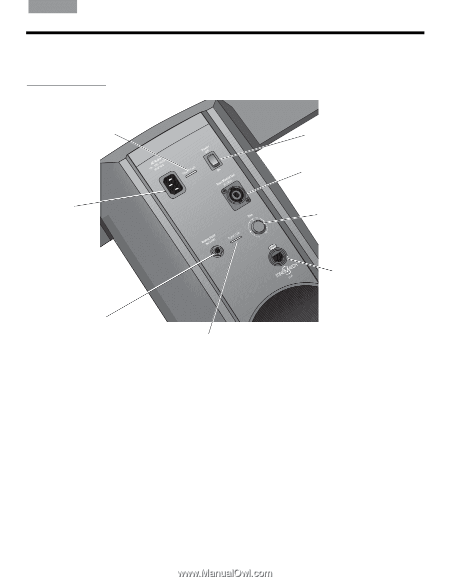
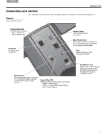
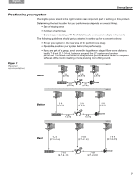
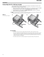
English DEDseapunatssñckohl FDItreaulnitaçsnacoihs NeEdsepralañnodl s FSrvaennçsakias Italiano Nederlands Svenska INTRODUCTION Connections and controls The top panel of the power stand provides system connectors and controls (Figure 2). Figure 2 Power stand top panel Power/Fault LED Indicates power status. Blue = system on Red = system fault AC Mains AC power input connector. Power switch Switches the system on and off. Bass Module Out Bass output signal for driving one or two B1 bass modules. Accepts a 4-wire bass module cable. Trim Adjusts the level of the analog input signal. Analog Input A line-level analog input. Accepts a ¼" TRS phone cable. Used for an instrument or other audio source. Signal/Clip LED Indicates status of the analog input signal. Green = normal input Yellow = input approaching clipping Red = input clipping ToneMatch® port Digital audio and power connection for the optional T1 ToneMatch audio engine. Accepts the included ToneMatch cable. 7 Venice_Intro.fm 4/12
-
 1
1 -
 2
2 -
 3
3 -
 4
4 -
 5
5 -
 6
6 -
 7
7 -
 8
8 -
 9
9 -
 10
10 -
 11
11 -
 12
12 -
13
-
14
-
15
-
16
-
17
-
18
-
19
-
20
-
21
-
22
 |
 |