Bose Lifestyle 3 Series II Owner's guide - Page 9
LE„, Connecting, Acoustimass°, module, Lifestyle, music, center
 |
View all Bose Lifestyle 3 Series II manuals
Add to My Manuals
Save this manual to your list of manuals |
Page 9 highlights
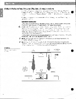
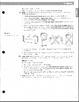
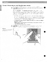
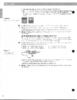
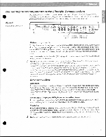
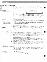
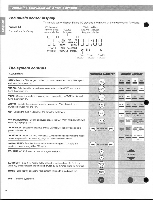
t4 :ViZgataitiVtr • Figure 5 - - Music center and speaker connections 110-120V 10 t CN` Connecting the Acoustimass° module to the Lifestyle' music center Connect the Acoustimass module to the music center with the audio input cable (Figure 5). 1. Insert the three connectors at one end of the audio input cable into the jacks on the rear panel of the music center: • Black connector into the SYSTEM CONTROL 1 jack • Red connector into the R (right) SPEAKERS A OUTPUT jack • White connector into the L (left) SPEAKERS A OUTPUT jack Note: Be sure the connectors are fully inserted into each of the jacks. lithe black connector is not inserted fully into the SYSTEM CONTROL jack, you will hear no sound. 2. Insert the three connectors at one end of the audio input cable into the jacks on the rear panel of the Acoustimass module: • Black connector into the SYSTEM CONTROL IN jack • Red connector into the R (right) AUDIO IN jack • White connector into the L (left) AUDIO IN jack 3. Extend the audio input cable as much as possible, since it includes an antenna for the remote control. re, '1q LE„4 220-240V Voltage selector switch Power O switch ?C* 171W14 Audio input cable Red and white connectors into matching SPEAKERS A OUTPUTs Black connector into SYSTEM CONTROL 1 •
-
 1
1 -
2
-
3
-
 4
4 -
 5
5 -
 6
6 -
 7
7 -
 8
8 -
 9
9 -
 10
10 -
 11
11 -
 12
12 -
 13
13 -
 14
14 -
15
-
16
-
17
-
18
-
19
-
20
-
21
-
22
-
23
-
24
-
25
-
26
 |
 |
