Boss Audio 460BRGB User Manual - Page 5
Installationcont. - wiring diagram
 |
View all Boss Audio 460BRGB manuals
Add to My Manuals
Save this manual to your list of manuals |
Page 5 highlights
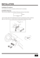
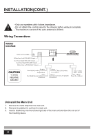
INSTALLATION(CONT.) - Only use speakers with 4 ohms impedance. ! - Do not attach the control panel to the chassis before wiring is complete. - The maximum current of the auto antenna is 200mA. Wiring Connections WIRING DIAGRAM 15A 15 Radio Antenna White:Front Left PRE-AMP Output Red: Front Right PRE-AMP Output Red: Rear Right PRE-AMP Output White: Rear Left PRE-AMP Output CAUTION +12V DC NEGATIVE GROUND Purple + Rear Right Speaker Purple/Black - Gray + Front Right Speaker Gray/Black - Green + Rear Left Speaker Green/Black - White + Front Left Speaker White/Black - ACC + (Red) GND - (Black) ANT + (Blue) Power B + (Yellow) Uninstall the Main Unit 1. Remove the metal strap from the main unit. 2. Remove the plastic trim out from the main unit. 3. Insert a bracket key into the left and right side of the main unit and draw the unit out of the mounting sleeve. 3
-
 1
1 -
 2
2 -
 3
3 -
 4
4 -
 5
5 -
 6
6 -
 7
7 -
 8
8 -
 9
9 -
 10
10 -
 11
11 -
12
-
13
-
14
 |
 |
