Boss Audio BV8974B User Manual - Page 18
Boss Audio BV8974B Manual
 |
View all Boss Audio BV8974B manuals
Add to My Manuals
Save this manual to your list of manuals |
Page 18 highlights
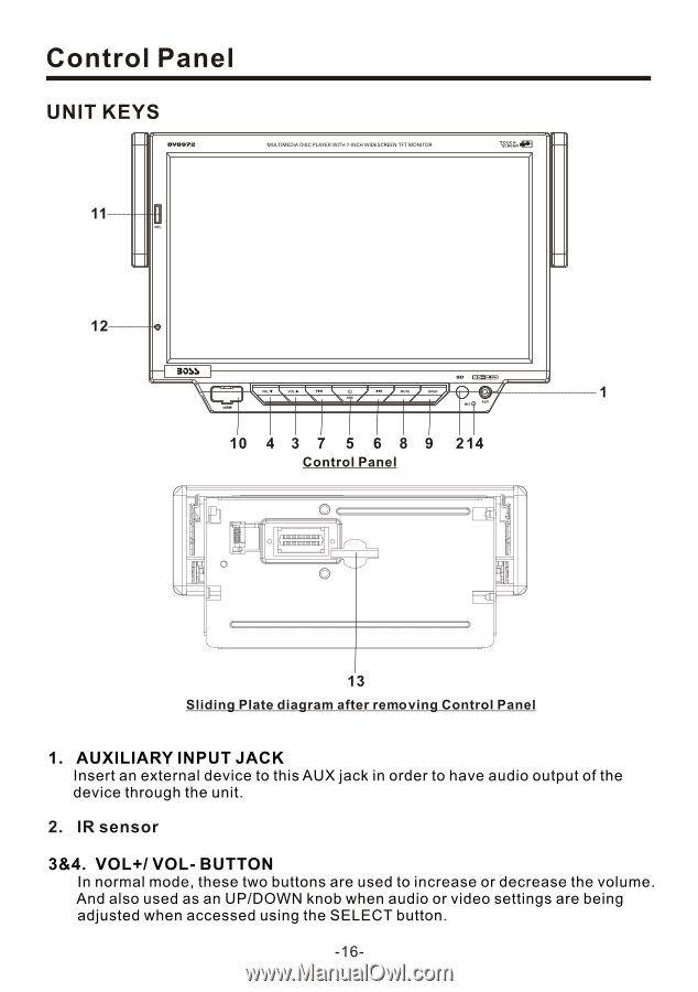
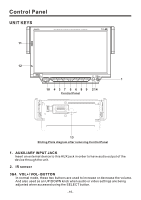
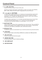
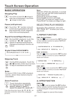
Control Panel UNIT KEYS 11 12 1 MIC 10 4 3 7 5 6 8 9 214 Control Panel 13 Sliding Plate diagram after remo ving Control Panel 1. AUXILIARY INPUT JACK Insert an external device to this AUX jack in order to have audio output of the device through the unit. 2. IR sensor 3&4. VOL+/ VOL- BUTTON In normal mode, these two buttons are used to increase or decrease the volume. And also used as an UP/DOWN knob when audio or video settings are being adjusted when accessed using the SELECT button. -16-
-
 1
1 -
2
-
3
-
4
-
5
-
6
-
7
-
8
-
9
-
10
-
11
-
12
-
 13
13 -
 14
14 -
 15
15 -
 16
16 -
 17
17 -
 18
18 -
 19
19 -
 20
20 -
 21
21 -
 22
22 -
 23
23 -
24
-
25
-
26
-
27
-
28
-
29
-
30
-
31
-
32
-
33
-
34
-
35
-
36
-
37
-
38
 |
 |