Brother International BAS-311F-0 Instruction Manual - English
Brother International BAS-311F-0 Manual
 |
View all Brother International BAS-311F-0 manuals
Add to My Manuals
Save this manual to your list of manuals |
Brother International BAS-311F-0 manual content summary:
- Brother International BAS-311F-0 | Instruction Manual - English - Page 1
BAS-311F-0, 311F-L BAS-326F-0 INSTRUCTION MANUAL Please read this manual before using the machine. Please keep this manual within easy reach for quick reference. PROGRAMMABLE ELECTRONIC PATTERN SEWER - Brother International BAS-311F-0 | Instruction Manual - English - Page 2
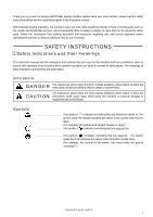
BROTHER sewing machine. Before using your new machine, please read the safety instructions below and the explanations given in the instruction manual. With industrial sewing machines, it is normal to carry out work while positioned directly in front of moving parts ".) BAS-311F-0, 311F-L, 326F-0 i - Brother International BAS-311F-0 | Instruction Manual - English - Page 3
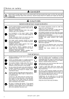
problems with correct operation. Installation Machine installation should only be carried out by a qualified technician. Contact your Brother and problems with correct operation may also occur. All cords should be secured at least 25 mm away from any moving parts. BAS-311F-0, 311F-L, 326F-0 ii - Brother International BAS-311F-0 | Instruction Manual - English - Page 4
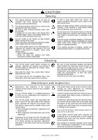
the power switch at the following times, otherwise the machine may operate if only the proper replacement parts as specified by Brother. If any safety problems in machine operation which result from unauthorized modifications to the machine will not be covered by the warranty. BAS-311F-0, 311F - Brother International BAS-311F-0 | Instruction Manual - English - Page 5
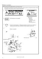
warning labels appear on the sewing machine. Please follow the instructions on the labels at all times when using the machine. If the labels have been removed or are difficult to read, please contact your nearest Brother dealer. 1 2 3 High temperature warning display Safety devices Eye guard - Brother International BAS-311F-0 | Instruction Manual - English - Page 6
MAJOR PARTS ...1 11 3-11. Connecting the cords (Installing the operation panel 11 BAS-311F-0 solenoid type only 16 3-18. Installing the feed base cover supports (BAS-311F-L, 326F-0 17 3-19. Installing the X feed base cover (BAS-311F 25 5-6-6. Adjusting arm thread guide R...25 6. USING THE - Brother International BAS-311F-0 | Instruction Manual - English - Page 7
...54 10-1. Panel DIP switch functions ...54 10-2. DIP swtiches inside the control box ...56 11. CHANGING SPECIAL FUNCTIONS AND USING THE MEMORY SWITCHES 58 12. ERROR CODES ...63 13. GAUGE PARTS LIST ACCORDING TO SUBCLASSES 66 14. TROUBLESHOOTING ...68 15. OPTIONS ...72 BAS-311F-0, 311F-L, 326F-0 - Brother International BAS-311F-0 | Instruction Manual - English - Page 8
1. NAME OF MAJOR PARTS (12) (11) (16) (8) (7) (3) (17) (10) (9) (20) (19) (4) (5) 1157S 1. NAME OF MAJOR PARTS (15) (18) (14) (1) (2) (1) Power (13) (9) Finger guard (10) Eye guard (11) Thread take-up cover (12) Belt cover (13) Frame side cover 1159S BAS-311F-0, 311F-L, 326F-0 1 - Brother International BAS-311F-0 | Instruction Manual - English - Page 9
length Maximum sewing speed Feed mechanism Single needle lock stitch Lock stitch, pattern tacking sewing machine (with large shuttle hook) BAS-311F-0: 130 X 60 mm, BAS-311F-L: 220 X 60 mm, BAS-326F-0: 220 X 100 mm 20,000 (one pattern) 0.05 - 12.7 mm 2,500 rpm (When stitch length is 3 mm or less - Brother International BAS-311F-0 | Instruction Manual - English - Page 10
Brother dealer or a qualified electrician for any electrical work that may need to be done. The sewing machine head weighs more than 65 kg (311F-0), 70 kg (311F be secured at least 25 mm away from any moving parts. Furthermore, do not excessively bend the cable or secure BAS-311F-0, 311F-L, 326F-0 3 - Brother International BAS-311F-0 | Instruction Manual - English - Page 11
incorrectly. [Standard] 3-2. Positioning 1290S Determine the position for the sewing machine, and then lock the casters (1) so that the sewing machine will not move. (1) 1161S BAS-311F-0, 311F-L, 326F-0 4 - Brother International BAS-311F-0 | Instruction Manual - English - Page 12
(6) and nuts (7) as shown in the illustration above. * At this time, leave a gap of approximately 1 mm between the work table and the top it does not cross over the outlet port of the cooling fan (11) Some specifications are not supplied with an accessory power switch (10 BAS-311F-0, 311F-L, 326F-0 5 - Brother International BAS-311F-0 | Instruction Manual - English - Page 13
nails (3) so that the oil pan (2) is not at an angle. 2. While pushing the oil pan (2) down from above, screw in the oil container (4). (3) (2) (4) 0055Q BAS-311F-0, 311F-L, 326F-0 6 - Brother International BAS-311F-0 | Instruction Manual - English - Page 14
when the machine head is tilted back. Therefore, this means that the sewing machine will not start if the switching plate is not installed. 9 15 11 1162S BAS-311F-0, 311F-L, 326F-0 7 - Brother International BAS-311F-0 | Instruction Manual - English - Page 15
two bolts. 4. Check that the head position switch is turned on as shown in Figure 1. 5. Connect the motor cord connector (8) to the accessory cord connector (9). BAS-311F-0, 311F-L, 326F-0 8 - Brother International BAS-311F-0 | Instruction Manual - English - Page 16
Note The sewing machine is packed without the X feed base cover L assembly (1) installed. BAS-311F-L BAS-326F-0 (3) (4) (3) (4) 1168S 1169S 2. Loosen the screws (4) which are holding the feed base cover support (3) on the left of the sewing machine (when looking from the front of the sewing - Brother International BAS-311F-0 | Instruction Manual - English - Page 17
3. INSTALLATION BAS-311F-L (4) BAS-326F-0 (4) 1170S 1171S 3. Move the presser arm assembly (4) as far as it will go in the direction of the arrow in to its original position. After tilting back the machine head, do not push the face plate or the pulley from above. BAS-311F-0, 311F-L, 326F-0 10 - Brother International BAS-311F-0 | Instruction Manual - English - Page 18
phase power supply Red 3-phase White power supply Black Yellow/Green Yellow/Greeen Connect to ground 0064Q 3-11. Connecting the cords (Installing the operation panel) (8) (1) (9) 40 mm (4) (3) (2) 1 mm that the code does not touch it. Front cover 1587Q BAS-311F-0, 311F-L, 326F-0 11 - Brother International BAS-311F-0 | Instruction Manual - English - Page 19
the pulley side from above. 7. Pass the cords (10) through the hole (11) near the hinge of the work table. Note If the cords are passed Note Make sure that the ground connections are secure in order to ensure safety. (1) (2) (3) (1) 1424S S1. Make hole in the - Brother International BAS-311F-0 | Instruction Manual - English - Page 20
). Note Check that the cords do not come into contact with the fan (21) and that they are not clamped by the cover at this time. BAS-311F-0, 311F-L, 326F-0 13 - Brother International BAS-311F-0 | Instruction Manual - English - Page 21
of the foot switch (2) into the connector (3) of the control box (1). (1) (3) (2) 1178S 3-14. Installing the spool stand Install the spool stand (1) to the table. (1) 0073Q BAS-311F-0, 311F-L, 326F-0 14 - Brother International BAS-311F-0 | Instruction Manual - English - Page 22
machine is used without these devices attached, injury may result. 3. INSTALLATION Install the eye guard assy (1) to the face plate with the two screws (2). (1) (2) 1180S BAS-311F-0, 311F-L, 326F-0 15 - Brother International BAS-311F-0 | Instruction Manual - English - Page 23
the work clamp lifter pedal (6) before tilting back the machine head. Move the treadle support base (8) back and forth to adjust so that the chain which is attached to the presser lifter connecting rod (4) and the presser lifter treadle (6) does not touch the cables. BAS-311F-0, 311F-L, 326F-0 16 - Brother International BAS-311F-0 | Instruction Manual - English - Page 24
3-18. Installing the feed base cover supports (BAS-311F-L, 326F-0) 3. INSTALLATION BAS-311F-L Coinside Coinside BAS-326F-0 Coinside (2) (3) (2(2) ) (2) (1) (1) 11116688SS 1169S 1186S Loosen the four screws (1) on the side of the bed by about 2-3 turns, and then install the feed base - Brother International BAS-311F-0 | Instruction Manual - English - Page 25
INSTALLATION 3-20. Connecting the tubes (pneumatic type only) 1188S BAS-311F-0, 311F-L BAS-326F-0 1189S Cylinder L Cylinder R Cylinder L Cylinder R Upper knob Lower knob Manual button 0319Q Connect each air tube to the position with the corresponding number. BAS-311F-0, 311F-L, 326F-0 18 - Brother International BAS-311F-0 | Instruction Manual - English - Page 26
pressing the switch. If the manual button is pushed in and turned to the right, the work clamp can then be held in the raised condition. Note The valve knobs should be adjusted so that the left and right sides of the work clamp operate at the same speed. BAS-311F-0, 311F-L, 326F-0 19 - Brother International BAS-311F-0 | Instruction Manual - English - Page 27
race base, problems with sewing may result, so add oil to the felt until it is slightly soaked. Note 4: Use only specified Brother oil (Nisseki Mitsubishi Sewing Lube 10N; VG10) for the machine oil. Lubrication points 1. Fill the arm-side oil tank with oil. BAS-311F-0, 311F-L 1190S BAS-326F - Brother International BAS-311F-0 | Instruction Manual - English - Page 28
the sewing machine and when it hasn't been used for an extended period of time, be sure to add 2-3 drops oil to the felt. 4. If using the 16 DP X 17 # 19 DP X 17 # 21 DP X 17 # 25 Thread #100 - #60 #80 - #50 #50 - #20 #50 - #20 #20 - #4 Main application Knitted wear BAS-311F-0, 311F-L, 326F-0 21 - Brother International BAS-311F-0 | Instruction Manual - English - Page 29
the needle hole and the end of the thread. If the trailing length of the thread is too long, it may cause the thread to. BAS-311F-0, 311F-L, 326F-0 22 - Brother International BAS-311F-0 | Instruction Manual - English - Page 30
not touch or place anything against any of the moving parts while winding the lower thread, otherwise personal injury or in the illustration at left, wind the thread around the bobbin several times in the direction of the arrow, and then press the bobbin presser BAS-311F-0, 311F-L, 326F-0 23 - Brother International BAS-311F-0 | Instruction Manual - English - Page 31
arrow when the thread is pulled at this time. 4. Pass the thread through the lever thread hole (4), and then pull out approximately 30 mm of thread. 5-6. Sewing conditions and thread tension 5-6-1. Sewing conditions Specifications Upper thread BAS-311F-0, 326F-0 For heavy materials For medium - Brother International BAS-311F-0 | Instruction Manual - English - Page 32
then move arm thread guide R (1). When sewing thick material, move arm thread guide R (1) to the left. (The thread take-up amount will become greater.) When sewing thin material, move arm thread guide R (1) to the right. (The thread take-up amount will become less.) BAS-311F-0, 311F-L, 326F-0 25 - Brother International BAS-311F-0 | Instruction Manual - English - Page 33
bobbin thread counter, split No.). One of the indicators (7) - (11) illuminates to indicate the menu selected, and the setting for that (5). The illuminated indicator changes in the following order each time the switch is pressed. X-SCALE indicator (7) Y-SCALE BAS-311F-0, 311F-L, 326F-0 26 - Brother International BAS-311F-0 | Instruction Manual - English - Page 34
COUNTER Illuminates when bobbin thread counter mode has been selected using the menu indicator switch (6). (11) SPLIT NO. indicator Illuminates when split No. mode has been selected using the menu switch broken needle thread. Also used to reset error displays. BAS-311F-0, 311F-L, 326F-0 27 - Brother International BAS-311F-0 | Instruction Manual - English - Page 35
these disks. Refer to the programmer instruction manual for details.) TFD embroidery data can be embroidered after it has been converted by the programmer to BAS-300F and BAS300E data. Restriction on Applicable command [668] L [669] L [220] L [230] L [221] L [231] L BAS-311F-0, 311F-L, 326F-0 28 - Brother International BAS-311F-0 | Instruction Manual - English - Page 36
cleaning disk will become short. Next time you clean it, select a different number. 3. After the cleaning is completed, the "E.4F" error appears. The error appears because the cleaning disk has no data. This is normal. 4. Cancel the error and eject the cleaning disk. BAS-311F-0, 311F-L, 326F-0 29 - Brother International BAS-311F-0 | Instruction Manual - English - Page 37
(when memory switch No. 0d is ON). If memory switch No. 0d is OFF, press the EMERGENCY STOP switch (7) once more to release it. 1216S BAS-311F-0, 311F-L, 326F-0 30 - Brother International BAS-311F-0 | Instruction Manual - English - Page 38
and the program number will stop flashing. This only occurs the first time that a program is (15) (17) selected. 4. Press the one stitch at a time. 1218S Resuming operation from a stopping poing 6. Sewing will start when the starting pedal (1) is pressed. BAS-311F-0, 311F-L, 326F-0 31 - Brother International BAS-311F-0 | Instruction Manual - English - Page 39
again. Press the TEST switch (15) again to stop the machine. 4. After you have reached the desired position, depress the starting pedal to start sewing. BAS-311F-0, 311F-L, 326F-0 32 - Brother International BAS-311F-0 | Instruction Manual - English - Page 40
setting is displayed as a percentage. (7) 3. The program number will flash, and after the home (8) position is detected the flashing will stop. 1221S (6) (12) (17) 1215S BAS-311F-0, 311F-L, 326F-0 33 - Brother International BAS-311F-0 | Instruction Manual - English - Page 41
in the counter (5) to the disk. 4. The number shown in the counter (5) will decrease one each time the stitch pattern is completed. When the number of patterns shown in the counter is sewn, the counter (5) set in step 3 will be displayed again in the counter (5). BAS-311F-0, 311F-L, 326F-0 34 - Brother International BAS-311F-0 | Instruction Manual - English - Page 42
), press the B.T. SET switch (13) The B.T. COUNTER indicator (10) and the SPLIT NO. indicator (11) will both illuminate, and the production counter value will appear on the program number display (2) and on the of each display screen will return to the normal display. BAS-311F-0, 311F-L, 326F-0 35 - Brother International BAS-311F-0 | Instruction Manual - English - Page 43
split sewing. 3. Press the MENU switch (6) until the SPLIT NO. indicator (11) is illuminated. "1" will then appear in the display screen (5). Then, while As to split sewing, refer to the instruction manual of the "electronic programmable pattern tacker programmer". BAS-311F-0, 311F-L, 326F-0 36 - Brother International BAS-311F-0 | Instruction Manual - English - Page 44
6. USING THE OPERATION PANEL 6-11. Shifting a stitch pattern Programs 5. Turn the setting dial (12) to move the feed mechanism one pulse at a time. If the setting dial is turned counterclockwise while the X-SCALE indicator is illuminated, the feed whole when moving it. BAS-311F-0, 311F-L, 326F-0 37 - Brother International BAS-311F-0 | Instruction Manual - English - Page 45
times, otherwise the machine may operate if the foot switch is depressed by mistake, which could result in injury. When replacing the bobbin and needle When not using the machine and when leaving the machine unattended Do not touch any of the moving parts 1229S 38 1213S BAS-311F-0, 311F-L, 326F-0 - Brother International BAS-311F-0 | Instruction Manual - English - Page 46
with small pieces which are hard to position, or when precise sewing is required, press the manual work clamp lifter pedal (7) for precise positioning of the work piece, and then press presser (7) since the machine will stores the sewing data from the last time. BAS-311F-0, 311F-L, 326F-0 39 - Brother International BAS-311F-0 | Instruction Manual - English - Page 47
ends from around the driver (4), the top of the rotary hook thread guide and the shuttle race. 8-2. Lubrication Note 1: Fill the machine with base, problems with sewing may result, so add oil to the felt until it is slightly soaked. Note 4: Use only specified Brother oil ( BAS-311F-0, 311F-L, 326F-0 - Brother International BAS-311F-0 | Instruction Manual - English - Page 48
thinner to clean the eye guard. 1235S 8-7. Checking the needle Always check that the tip of the needle is not broken before starting sewing. 1236S BAS-311F-0, 311F-L, 326F-0 41 - Brother International BAS-311F-0 | Instruction Manual - English - Page 49
a qualified technician. Ask your Brother dealer or a qualified electrician to from the wall outlet at the following times, otherwise the machine may operate if inspection, adjustment and maintenance When replacing consumable parts such as the rotary hook and knife Hold BAS-311F-0, 311F-L, 326F-0 42 - Brother International BAS-311F-0 | Instruction Manual - English - Page 50
is 0.01 - 0.08 guide (1) by pushing it in the direction of the arrow so that the needle groove is aligned with the center of the needle plate hole. Note If the shuttle race thread guide is in the wrong position, thread breakages, soiled thread or catching of the thread may occur. BAS-311F-0, 311F - Brother International BAS-311F-0 | Instruction Manual - English - Page 51
needle plate when in this condition (the procedure 3.) and the movable knife (1) is pushed to the machine pulley side so that there is no play. BAS-311F-0, 311F-L, 326F-0 44 - Brother International BAS-311F-0 | Instruction Manual - English - Page 52
the screw. D. Turn the movable knife (in the direction of the arrow) while the screw is still loosened. Repeat above steps A, B, C and D four or five times to maintain the cutting performance of the knife. 0150Q BAS-311F-0, 311F-L, 326F-0 45 - Brother International BAS-311F-0 | Instruction Manual - English - Page 53
diameter pin (such as a needle) to align the hole in the (1) needle plate (5) with the hole in the feed plate (2) BAS-311F-0, -L "when the machine is at the home position", BAS-326F-0 "when the sewing machine has moved 20 mm (400 pulses) backward (in the Y direction) from the home position" and - Brother International BAS-311F-0 | Instruction Manual - English - Page 54
) (13) (11) (12) (10) 1255S 1256S If vertical movement of the presser foot is not required 1. Remove the face plate (10). 2. Remove the stud screw (11) and re-attach the intermitte connecting rod (12) to the upper screw hole (14) of the intermittent presser arm F (13). BAS-311F-0, 311F-L, 326F - Brother International BAS-311F-0 | Instruction Manual - English - Page 55
(2) 25 mm 25 mm 35 mm 35 mm 1260S 1262S 1263S 1. Loosen the set screw (2) and move the wiper arm support (3) up or down to adjust so that there is a clearance of 15 16 mm between the bottom of the thread wiper to adjust so that the distance is approximately 25 mm. BAS-311F-0, 311F-L, 326F-0 48 - Brother International BAS-311F-0 | Instruction Manual - English - Page 56
plate. The lift amount for each model is adjusted as shown in the table at the time of shipment. type Solenoid type (BAS-311F-0 only) Lift amount 17 mm Pneumatic type 20 mm 9-10-1. BAS-311F-0 Solenoid type (3) 20 mm (2) (1) 1264S 1. Turn the power switch OFF. 2. Loosen the bolts (2) of work - Brother International BAS-311F-0 | Instruction Manual - English - Page 57
9. STANDARD ADJUSTMENTS 9-10-3. BAS-326F-0 1268S (3) (2) (4) (3) (2) (4) (5) (5) (1) 1304S 1269S 20 mm Scale 1270S 1. Turn on the air, and then press the presser indicated by an arrow to drain the water. Note Open the air cock (4) slowly. (1) (3) 1271S BAS-311F-0, 311F-L, 326F-0 50 - Brother International BAS-311F-0 | Instruction Manual - English - Page 58
9. STANDARD ADJUSTMENTS 9-11. Adjusting the needle up stop position The needle up stop position is adjusted so that the index mark (2) on the Turn the machine pulley to move the index mark (2) to the correct position and then start the sewing 1272S machine. BAS-311F-0, 311F-L, 326F-0 51 - Brother International BAS-311F-0 | Instruction Manual - English - Page 59
row of the program number display (7). 1284S 4. If the settings for DIP switch B are changed at this time, the number of the changed switch will appear in the bottom row of the program number display (7). 1285S be turned off before DIP switch settings can be changed. BAS-311F-0, 311F-L, 326F-0 52 - Brother International BAS-311F-0 | Instruction Manual - English - Page 60
operation causes memory switch settings to be returned to their initial settings, and also clears all contents of the memory such as sewing datas. 1278S (1) BAS-311F-0, 311F-L, 326F-0 1279S 53 - Brother International BAS-311F-0 | Instruction Manual - English - Page 61
10. DIP SWITCH 10. DIP SWITCH Note All DIP switches are set to OFF at the time of shipment. When changing DIP switch, the power must be off. 10-1. Panel DIP switch functions Air Lowers in the order left and right work clamp, presser foot; reverse order when rising. BAS-311F-0, 311F-L, 326F-0 54 - Brother International BAS-311F-0 | Instruction Manual - English - Page 62
, the presser foot will drop at the same time that both work clamps drop. B-8 Feeding speed is switched to high speed. * If using the work clamp and sewing data for the older BAS-311EL model, set DIP switch B -2 ON. The BAS-311 L-type has a different length for the sewing area - Brother International BAS-311F-0 | Instruction Manual - English - Page 63
connection has been changed so that the work clamp remains raised when the power is turned off. C-6 When using an air-driven intermittent work clamp C-7 - C-8 - BAS-311F-0, 311F-L, 326F-0 56 - Brother International BAS-311F-0 | Instruction Manual - English - Page 64
. As a result, the thread take-up will rise slightly at the sewing start, and this may result in the thread pulling out under certain conditions. BAS-311F-0, 311F-L, 326F-0 57 - Brother International BAS-311F-0 | Instruction Manual - English - Page 65
11. CHANGING SPECIAL FUNCTIONS AND USING THE MEMORY SWITCHES The functions of the switches on the operation panel can be changed to carry out special functions. * All of the memory switches are set to OFF at the time switch settings will be written to the floppy disk. BAS-311F-0, 311F-L, 326F-0 58 - Brother International BAS-311F-0 | Instruction Manual - English - Page 66
11. CHANGING SPECIAL FUNCTION AND USING THE MEMORY SWITCHES Memory switches (00 - 0F) Switch No. memo-00 memo-01 memo-02 memo-03 memo-04 memo-05 memo-06 memo-07 memo-08 memo-09 closes once. (practice operation) If memo-0E is ON, the work clamp opens and closes twice. BAS-311F-0, 311F-L, 326F-0 59 - Brother International BAS-311F-0 | Instruction Manual - English - Page 67
AND USING THE MEMORY SWITCHES Memory switches (10 - 1F) Switch No. memo-10 memo-11 memo-12 memo-13 memo-14 memo-15 memo-16 memo-17 memo-18 memo-19 memo Program number is changed automatically by using outside switch. (Use optional connector P3 on the operation panel.) BAS-311F-0, 311F-L, 326F-0 60 - Brother International BAS-311F-0 | Instruction Manual - English - Page 68
11 During feed test operation, jump feeding 100 stitches at a time is possible using the STEP BACK switch. After the home Set to ON when the bobbin changer is being used. (This part is available by special order.) Feed operation is enabled even if Brother Sales Office. BAS-311F-0, 311F-L, 326F-0 61 - Brother International BAS-311F-0 | Instruction Manual - English - Page 69
BAS-311F solenoid specifications 40 only). 10 (Quiet) 60 (High work clamp capacity) 1 The solenoid ON time when the presser foot is raised changes. (Standard) 1 3 (Upper limit) Automatically corrects the gear speed when reading 2DD disks. 0 : No automatic correction 0 1 : Read as BAS-311A - Brother International BAS-311F-0 | Instruction Manual - English - Page 70
problem occurs E.11 timing mark with that on belt cover. Data exceeds available sewing area due to resize Adjust resize ratio. ratio. Stitch length exceeds 12.7mm due to resize ratio. Adjust resize ratio. No end code in sewing data. Input end code, or change program No. BAS-311F-0, 311F - Brother International BAS-311F-0 | Instruction Manual - English - Page 71
program No.. E.43 E.4F E.50 E.51 E.52 E.5F E.60 Different floppy disk! Error occurred during floppy disk data reading. Floppy overload. E.80 Upper thread has broken. (Rotary type sensor) See the manual for Milling motor. If not use milling motor, set OFF memory switch BAS-311F-0, 311F-L, 326F-0 64 - Brother International BAS-311F-0 | Instruction Manual - English - Page 72
P20. PCB and main PCB. Over current at power supply PCB. Turn off power and check it. REFERENCE segment LED alphabet Panel display Text display A B C D E F 6 H L O BAS-311F-0, 311F-L, 326F-0 65 - Brother International BAS-311F-0 | Instruction Manual - English - Page 73
further flexibility to the range of applications. Subclass Part name/ Specification Needle hole plate 0182Q Bobbin case 0191Q Needle bar thread guide 1639S Needle assy Needle 0193Q Presser foot 1288S Feed plate 311 1289S 1S, 4S Heavy materials (Solenoid type) BAS-311F-0 2A Medium materials - Brother International BAS-311F-0 | Instruction Manual - English - Page 74
0191Q Needle bar thread guide 1639S Needle assy Needle 0193Q Presser foot 1288S Feed plate 311 1289S 13. GAUGE PARTS LIST ACCORDING TO SUBCLASSES 1A Heavy materials BAS-326F-0 2A Medium materials 001 A S55952-001 A SA1645-019 DP X 17#19 145646-019 S55953-001 B BAS-311F-0, 311F-L, 326F-0 67 - Brother International BAS-311F-0 | Instruction Manual - English - Page 75
14. TROUBLESHOOTING 14. TROUBLESHOOTING Problem Cause Check Remedy Page Presser does not rise. Work clamp operation Sliding part of the work Grease the sliding part of is sluggish. clamp lubrication the work clamp. Presser lifter air tube is bent or damaged.* Pressure lifter air tube - Brother International BAS-311F-0 | Instruction Manual - English - Page 76
Problem Cause Check 14. TROUBLESHOOTING burring File smooth or replace the affected part. Thread melting (synthetic thread) Thread . Incorrect needle and rotary hook timing. Driver is contacting needle more is too thin. Needle and thread BAS-311F-0, 311F-L, 326F-0 Adjust the needle clearance. - Brother International BAS-311F-0 | Instruction Manual - English - Page 77
14. TROUBLESHOOTING Problem Cause Check Remedy Page Upper thread is not trimmed. Fixed knife is blunt. Fixed knife blade Movable knife does not pick up the thread. Shuttle race thread guide position Needle tension and height of the thread takeup spring. 25 70 BAS-311F-0, 311F-L, 326F-0 - Brother International BAS-311F-0 | Instruction Manual - English - Page 78
Problem Cause Check 14. TROUBLESHOOTING or replace the fixed knife. Unstable needle up stop position Electrical trouble Refer to the details for [E.22] in the error code table is 11 13 Adjust the position of the switching plate. 7 Replace the head position switch. BAS-311F-0, 311F-L, 326F - Brother International BAS-311F-0 | Instruction Manual - English - Page 79
or aluminum sheets. This device is available by special order. Please contact your nearest Brother dealer. Increases the stitch creation range for perfect stitches. Automatic bobbin changer Snap fastener sewing when a thread breakage is detected and warns the operator. BAS-311F-0, 311F-L, 326F-0 72 - Brother International BAS-311F-0 | Instruction Manual - English - Page 80
materials where normal trailing thread lengths can often lead to the thread pulling out. (311F series: Solenoid type, 326F: Pneumatic type) Automatic ejector When the reflective plate cassette is ejected automatically. * Refer to the separate Parts Book for details. BAS-311F-0, 311F-L, 326F-0 73 - Brother International BAS-311F-0 | Instruction Manual - English - Page 81
INSTRUCTION MANUAL 15-1, Naeshiro-cho, Mizuho-ku, Nagoya 467-8561, Japan. Phone: 81-52-824-2177 Printed in Japan BAS-311F SA3024-001 2003.08.H (1)
-
 1
1 -
 2
2 -
 3
3 -
 4
4 -
 5
5 -
 6
6 -
 7
7 -
8
-
9
-
10
-
11
-
12
-
13
-
14
-
15
-
16
-
17
-
18
-
19
-
20
-
21
-
22
-
23
-
24
-
25
-
26
-
27
-
28
-
29
-
30
-
31
-
32
-
33
-
34
-
35
-
36
-
37
-
38
-
39
-
40
-
41
-
42
-
43
-
44
-
45
-
46
-
47
-
48
-
49
-
50
-
51
-
52
-
53
-
54
-
55
-
56
-
57
-
58
-
59
-
60
-
61
-
62
-
63
-
64
-
65
-
66
-
67
-
68
-
69
-
70
-
71
-
72
-
73
-
74
-
75
-
76
-
77
-
78
-
79
-
80
-
81
 |
 |
BAS-311F-0, 311F-L
BAS-326F-0
Please read this manual before using the machine.
Please keep this manual within easy reach for quick reference.
PROGRAMMABLE ELECTRONIC PATTERN SEWER
INSTRUCTION MANUAL