Brother International CV3550 Operation Manual - Page 10
Powering the machine, Turning direction of, handwheel, Opening/Closing front cover, Attaching/
 |
View all Brother International CV3550 manuals
Add to My Manuals
Save this manual to your list of manuals |
Page 10 highlights
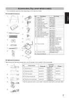
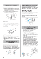
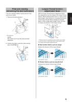
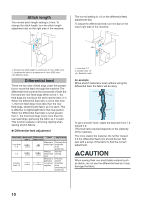
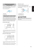
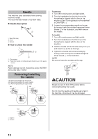
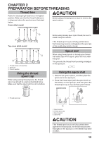
Powering the machine „„Turning on the machine 1. Insert the three-pin plug into the socket on the lower-right side of the machine. Insert the power supply plug into a power outlet. 2. Turn the main power and light switch to "I" mark (to "O" mark to turn off). $! Opening/Closing front cover It is necessary to open the front cover when threading this machine. Slide it to the right 1, and then open it 2. After closing it, slide it to the left. CAUTION For your safety, make sure that the front cover is closed when operating the machine. Always turn off the machine before opening the front cover. a „„ Operation When the foot controller is pressed lightly, the machine runs at a low speed. As the foot controller is pressed further, the machine will increase speed. When the foot controller is released, the machine stops. NOTE (For U.S.A. only): Foot controller: Model KD-1902 This foot controller can be used on the machine with product code 884-B30 and 884-B31. * The product code is shown on the machine rating plate. Turning direction of handwheel The handwheel turns in a counterclockwise direction (direction of arrow). This is the same direction as an ordinary home sewing machine. Move the needles to their highest positions by turning the handwheel so that the mark on the handwheel is aligned with the line on the machine. $! %! 8 b Attaching/Removing a presser foot 1. Turn off the main power and light switch or disconnect the power supply plug. 2. Raise the presser foot lever 1. 3. Turn the handwheel 2 so that the line on the handwheel is aligned with the line on the machine. (See "Turning direction of handwheel" in CHAPTER 1.) 4. Push the button on the presser foot holder 3 to release the standard presser foot. 5. Raise the presser foot farther by pushing the presser foot lever upward. Then, remove the presser foot and store it in a safe location. 6. Again, raise the presser foot farther by pushing the presser foot lever upward. Place the presser foot just under the presser foot holder so that the groove in the bottom of the presser foot holder is aligned with the bar on the top of the foot , and then lower the presser foot lever to attach the foot 4. d a a bc b d
-
 1
1 -
2
-
3
-
4
-
 5
5 -
 6
6 -
 7
7 -
 8
8 -
 9
9 -
 10
10 -
 11
11 -
 12
12 -
 13
13 -
 14
14 -
 15
15 -
16
-
17
-
18
-
19
-
20
-
21
-
22
-
23
-
24
-
25
-
26
-
27
-
28
-
29
-
30
-
31
-
32
-
33
-
34
-
35
-
36
-
37
-
38
-
39
-
40
-
41
-
42
-
43
-
44
-
45
-
46
-
47
-
48
-
49
-
50
-
51
-
52
-
53
-
54
-
55
-
56
-
57
-
58
-
59
-
60
-
61
-
62
-
63
-
64
-
65
-
66
-
67
-
68
 |
 |
