Brother International DA-9270 Instruction Manual - English - Page 20
Caution, Standard Adjustments
 |
View all Brother International DA-9270 manuals
Add to My Manuals
Save this manual to your list of manuals |
Page 20 highlights
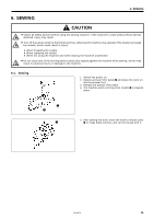
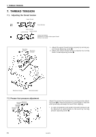
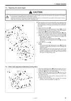
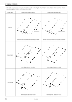
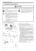
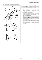
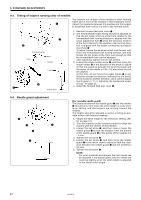
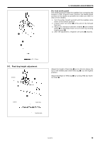
9. STANDARD ADJUSTMENTS 9. STANDARD ADJUSTMENTS CAUTION ¡ Maintenance and inspection of the sewing machine should only be carried out by qualified personnel. ¡ Ask your Brother dealer or a qualified electrician to carry out any maintenance and inspection of the electrical system. ¡ Turn off the power switch and disconnect the power cord from the wall outlet at the following times, otherwise the machine may operate if the treadle is pressed by mistake, which could result in injury. However, the motor will keep turning even after the power is switched off as a result of the motor's inertia. Wait until the motor stops fully before starting work. ¡ When carrying out inspection, adjustment and maintenance ¡ When replacing consumable parts such as the looper ¡ If the power switch needs to be left on when carrying out some adjustment, be extremely careful to observe all safety precautions. ¡ If any safety devices have been removed, be absolutely sure to re-install them to their original positions and check that they operate correctly before using the machine. 9-1. Needle bar height adjustment o !0 q i w u y e w 11.3mm (For thin materials) 10.1mm (For mediumthick materials) r t y 0 q i 0 q Adjust the heights of the needles q. At this time, adjust so that each needle q is in the center of the needle hole i in the needle plate w. 1. Remove the screw o, and then remove the presser foot !.0 2. Turn the machine pulley to drop the needle bar to its lowest position. 3. Remove the rubber plug r, loosen the needle bar clamp screw t and adjust so that the distance between the bottom of the needle clamp e and the top of the needle plate w is 11.3 mm (for thin materials) or 10.1 mm (for medium-thick materials). * If the needle clamp is set in the way described above, the distance between the points of the needles q and the top of the needle plate w will be 8.5 mm (for thin materials) or 10.3 mm (for mediumthick materials) when the needle clamp e is raised to its highest position. 4. Remove the three screws u, and then remove the needle plate w. 5. Turn the machine pulley so that the needles q and the needle guard y are aligned, and then adjust the tilt of the needle clamp e so that there is no space between the left and right needles q and the needle guard y at this time. Install the needle plate w with the three screws u, and after checking that the needles q are in the centers of the needle holes i, tighten the needle bar clamp screw t. 6. Insert the rubber plug r. 7. Install the presser foot !0 with the screw o. 15 DA-9270
-
 1
1 -
2
-
3
-
4
-
5
-
6
-
7
-
8
-
9
-
10
-
11
-
12
-
13
-
14
-
 15
15 -
 16
16 -
 17
17 -
 18
18 -
 19
19 -
 20
20 -
 21
21 -
 22
22 -
 23
23 -
 24
24 -
 25
25 -
26
-
27
-
28
 |
 |
