Brother International DA-9270 Instruction Manual - English - Page 24
Upper thread take-up thread guide adjustment, Upper thread arm thread guide adjustment, Thread
 |
View all Brother International DA-9270 manuals
Add to My Manuals
Save this manual to your list of manuals |
Page 24 highlights
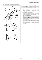
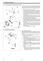
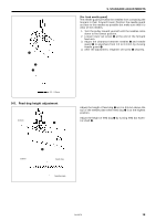
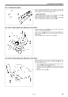
9. STANDARD ADJUSTMENTS 9-6. Upper thread take-up thread guide adjustment Adjust the distance between the center of the upper thread take-up and the top of the thread guide will be 2 ~ 3 mm. q w 1. Turn the pulley toward yourself until the needle bar is down at the lowest position. 2. Loosen the screw q, and then move the upper thread take-up thread guide w up or down to adjust so that the distance from the top of the upper thread take-up thread guide w to the center of the upper thread take- up hole is 2 - 3 mm. 2 - 3mm * The higher the upper thread take-up thread guide w, the greater will be the upper thread loops. 3. Tighten the screw q. 9-7. Upper thread arm thread guide adjustment Adjust the upper thread arm thread guide so that the upper thread has a slight tension when the loopers run out of upper thread loops. 1. Loosen the screw q, and then adjust so that the upper thread arm thread guide w is nearly horizontal. 2. After the adjustment, retighten the screw q. w q 9-8. Thread release shaft adjustment q w Adjust the thread release shaft so that the thread tension discs loosen when the presser foot is raised and tighten when the presser foot is lowered. 1. Loosen set screw q. 2. Make an adjustment by turning thread release shaft w so that the thread tension discs begin to loosen when the presser foot rises 4 mm above the top of the needle plate. 3. After the adjustment, retighten set screw q securely. 9-9. Lower thread take-up timing adjustment Adjusting hole w e 7mm q r Make an adjustment so that, when the loopers begin moving backward, lower thread take-up q contacts thread w, and is 7 mm up from lower thread take-up base e. 1. Insert screwdriver through the adjusting hole in the lower thread take-up base, and loosen two set screws r. 2. Raise lower thread take-up q until it is 7 mm up from thread take-up base e. 3. After the adjustment, retighten two set screws r securely. 19 DA-9270
-
 1
1 -
2
-
3
-
4
-
5
-
6
-
7
-
8
-
9
-
10
-
11
-
12
-
13
-
14
-
15
-
16
-
17
-
18
-
 19
19 -
 20
20 -
 21
21 -
 22
22 -
 23
23 -
 24
24 -
 25
25 -
 26
26 -
 27
27 -
 28
28
 |
 |
