Brother International HL-5150D Service Manual - Page 211
Fixing Unit failure, Main PCB failure, Be warned, however, that
 |
View all Brother International HL-5150D manuals
Add to My Manuals
Save this manual to your list of manuals |
Page 211 highlights
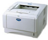
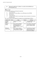
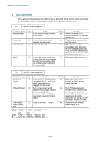
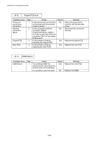
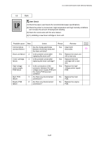
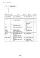
HL-5130/5140/5150D/5170DN SERVICE MANUAL M-9 Fixing Unit failure Possible cause Poor thermistor harness contact Blown thermal fuse Thermistor failure Halogen heater lamp failure Heater harness connection failure Step 1 2 3 4 5 Check Is the contact of connector CN7 on the engine PCB good? Remove the fixing unit and measure the resistance between the input connectors. Is it open circuit? Is the thermistor installed properly? Remove the fixing unit and measure the resistance of the halogen heater lamp. Is it open circuit? Is the heater harness connector connected to the low-voltage power supply PCB and fixing unit secure? Result No Yes Yes No Yes No Remedy Reconnect the connector. Replace the fixing unit. Replace the fixing unit. Reinstall the thermistor properly. Replace the halogen heater lamp. Reconnect the connectors securely. NOTE: • This problem will be cleared if leaving the printer power ON for ten minutes. • If the heater is cooled down sufficiently, this problem may be cleared by turning on the printer power switch while pressing the Job Cancel button. Be warned, however, that this operation will melt the fixing unit if the heater is hot. M-10 Main PCB failure Possible cause Main PCB Software bug Step 1 2 Check Is it possible to print the test page with the method of 1.3. 'INSPECTION MODE' in Chapter 7? Does this problem appear when printing specific data or printing under a specific environment? Result Remedy No Replace the main PCB. Yes Inform the Brother office of the used specific data, printer condition and system environment. 6-23
-
 1
1 -
2
-
3
-
4
-
5
-
6
-
7
-
8
-
9
-
10
-
11
-
12
-
13
-
14
-
15
-
16
-
17
-
18
-
19
-
20
-
21
-
22
-
23
-
24
-
25
-
26
-
27
-
28
-
29
-
30
-
31
-
32
-
33
-
34
-
35
-
36
-
37
-
38
-
39
-
40
-
41
-
42
-
43
-
44
-
45
-
46
-
47
-
48
-
49
-
50
-
51
-
52
-
53
-
54
-
55
-
56
-
57
-
58
-
59
-
60
-
61
-
62
-
63
-
64
-
65
-
66
-
67
-
68
-
69
-
70
-
71
-
72
-
73
-
74
-
75
-
76
-
77
-
78
-
79
-
80
-
81
-
82
-
83
-
84
-
85
-
86
-
87
-
88
-
89
-
90
-
91
-
92
-
93
-
94
-
95
-
96
-
97
-
98
-
99
-
100
-
101
-
102
-
103
-
104
-
105
-
106
-
107
-
108
-
109
-
110
-
111
-
112
-
113
-
114
-
115
-
116
-
117
-
118
-
119
-
120
-
121
-
122
-
123
-
124
-
125
-
126
-
127
-
128
-
129
-
130
-
131
-
132
-
133
-
134
-
135
-
136
-
137
-
138
-
139
-
140
-
141
-
142
-
143
-
144
-
145
-
146
-
147
-
148
-
149
-
150
-
151
-
152
-
153
-
154
-
155
-
156
-
157
-
158
-
159
-
160
-
161
-
162
-
163
-
164
-
165
-
166
-
167
-
168
-
169
-
170
-
171
-
172
-
173
-
174
-
175
-
176
-
177
-
178
-
179
-
180
-
181
-
182
-
183
-
184
-
185
-
186
-
187
-
188
-
189
-
190
-
191
-
192
-
193
-
194
-
195
-
196
-
197
-
198
-
199
-
200
-
201
-
202
-
203
-
204
-
205
-
 206
206 -
 207
207 -
 208
208 -
 209
209 -
 210
210 -
 211
211 -
 212
212 -
 213
213 -
 214
214 -
 215
215 -
 216
216 -
217
-
218
-
219
-
220
-
221
-
222
-
223
-
224
-
225
-
226
-
227
-
228
-
229
-
230
-
231
-
232
-
233
-
234
-
235
-
236
-
237
-
238
-
239
-
240
-
241
-
242
-
243
-
244
-
245
-
246
-
247
-
248
-
249
-
250
-
251
-
252
-
253
-
254
-
255
-
256
-
257
-
258
-
259
-
260
-
261
-
262
-
263
-
264
-
265
-
266
-
267
-
268
-
269
-
270
-
271
-
272
-
273
-
274
-
275
-
276
-
277
-
278
-
279
-
280
 |
 |