Brother International PC-7000 Users Manual - English - Page 5
Principal, Parts
 |
View all Brother International PC-7000 manuals
Add to My Manuals
Save this manual to your list of manuals |
Page 5 highlights
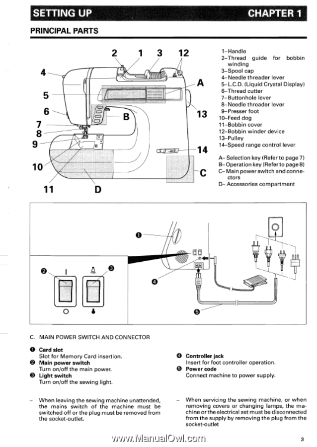
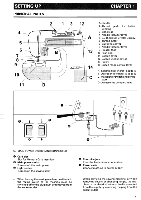
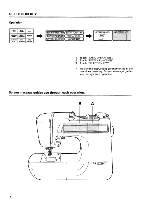
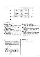
SETTING UP PRINCIPAL PARTS 6 7 8 9 s el 10' 11 CHAPTER 1 12 -)N 13 14 C 1-Handle 2-Thread guide for bobbin winding 3-Spool cap 4-Needle threader lever 5-L.C.D. (Liquid Crystal Display) 6-Thread cutter 7-Buttonhole lever 8-Needle threader lever 9-Presser foot 10-Feed dog 11-Bobbin cover 12-Bobbin winder device 13-Pulley 14-Speed range control lever A- Selection key (Refer to page 7) B- Operation key (Refer to page 8) C- Main power switch and conne- ctors D- Accessories compartment O 4 C. MAIN POWER SWITCH AND CONNECTOR O Card slot Slot for Memory Card insertion. • Main power switch Turn on/off the main power. • Light switch Turn on/off the sewing light. When leaving the sewing machine unattended, the mains switch of the machine must be switched off or the plug must be removed from the socket-outlet. O Controller jack Insert for foot controller operation. • Power code Connect machine to power supply. - When servicing the sewing machine, or when removing covers or changing lamps, the machine or the electrical set must be disconnected from the supply by removing the plug from the socket-outlet 3
-
 1
1 -
 2
2 -
 3
3 -
 4
4 -
 5
5 -
 6
6 -
 7
7 -
 8
8 -
 9
9 -
 10
10 -
 11
11 -
12
-
13
-
14
-
15
-
16
-
17
-
18
-
19
-
20
-
21
-
22
-
23
-
24
-
25
-
26
-
27
-
28
-
29
-
30
-
31
-
32
-
33
-
34
-
35
-
36
-
37
-
38
-
39
-
40
-
41
-
42
-
43
-
44
-
45
-
46
-
47
-
48
-
49
-
50
-
51
-
52
-
53
-
54
-
55
-
56
-
57
-
58
-
59
-
60
-
61
-
62
-
63
-
64
-
65
-
66
-
67
-
68
-
69
-
70
-
71
-
72
-
73
-
74
-
75
-
76
-
77
-
78
-
79
-
80
-
81
-
82
-
83
-
84
-
85
-
86
-
87
-
88
-
89
-
90
-
91
-
92
-
93
-
94
-
95
-
96
-
97
-
98
-
99
-
100
-
101
-
102
-
103
-
104
-
105
-
106
-
107
-
108
-
109
-
110
-
111
-
112
-
113
-
114
-
115
-
116
-
117
-
118
-
119
-
120
-
121
-
122
 |
 |