Brother International PR-600 Users Manual - English - Page 189
the two lower thumb screws to secure the cap
 |
View all Brother International PR-600 manuals
Add to My Manuals
Save this manual to your list of manuals |
Page 189 highlights
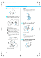
Sapphire.book Page 171 Friday, August 1, 2003 9:12 AM Insert the pins on the frame-mounting plate of 5 the carriage into the holes in the mounting plate of the cap frame driver. ■ Installing the needle plate spacer Attach the needle plate spacer to the needle plate. 1 1 2 1 Pins on the frame-mounting plate of the carriage 2 Holes in the mounting plate of the cap frame driver Tighten the two upper thumb screws. 6 1 Needle plate spacer While pushing in the cap frame driver toward 7 the machine so that it is fully inserted, tighten the two lower thumb screws to secure the cap frame driver. 7 X This completes the installation of the cap frame driver. Using the Optional Cap Frame 171
-
 1
1 -
2
-
3
-
4
-
5
-
6
-
7
-
8
-
9
-
10
-
11
-
12
-
13
-
14
-
15
-
16
-
17
-
18
-
19
-
20
-
21
-
22
-
23
-
24
-
25
-
26
-
27
-
28
-
29
-
30
-
31
-
32
-
33
-
34
-
35
-
36
-
37
-
38
-
39
-
40
-
41
-
42
-
43
-
44
-
45
-
46
-
47
-
48
-
49
-
50
-
51
-
52
-
53
-
54
-
55
-
56
-
57
-
58
-
59
-
60
-
61
-
62
-
63
-
64
-
65
-
66
-
67
-
68
-
69
-
70
-
71
-
72
-
73
-
74
-
75
-
76
-
77
-
78
-
79
-
80
-
81
-
82
-
83
-
84
-
85
-
86
-
87
-
88
-
89
-
90
-
91
-
92
-
93
-
94
-
95
-
96
-
97
-
98
-
99
-
100
-
101
-
102
-
103
-
104
-
105
-
106
-
107
-
108
-
109
-
110
-
111
-
112
-
113
-
114
-
115
-
116
-
117
-
118
-
119
-
120
-
121
-
122
-
123
-
124
-
125
-
126
-
127
-
128
-
129
-
130
-
131
-
132
-
133
-
134
-
135
-
136
-
137
-
138
-
139
-
140
-
141
-
142
-
143
-
144
-
145
-
146
-
147
-
148
-
149
-
150
-
151
-
152
-
153
-
154
-
155
-
156
-
157
-
158
-
159
-
160
-
161
-
162
-
163
-
164
-
165
-
166
-
167
-
168
-
169
-
170
-
171
-
172
-
173
-
174
-
175
-
176
-
177
-
178
-
179
-
180
-
181
-
182
-
183
-
 184
184 -
 185
185 -
 186
186 -
 187
187 -
 188
188 -
 189
189 -
 190
190 -
 191
191 -
 192
192 -
 193
193 -
 194
194 -
195
-
196
-
197
-
198
-
199
-
200
-
201
-
202
-
203
-
204
-
205
-
206
-
207
-
208
-
209
-
210
-
211
-
212
-
213
-
214
-
215
-
216
-
217
-
218
-
219
-
220
-
221
-
222
-
223
-
224
-
225
-
226
-
227
 |
 |

Using the Optional Cap Frame
171
7
5
Insert the pins on the frame-mounting plate of
the carriage into the holes in the mounting
plate of the cap frame driver.
1
Pins on the frame-mounting plate of the carriage
2
Holes in the mounting plate of the cap frame
driver
6
Tighten the two upper thumb screws.
7
While pushing in the cap frame driver toward
the machine so that it is fully inserted, tighten
the two lower thumb screws to secure the cap
frame driver.
This completes the installation of the cap
frame driver.
■
Installing the needle plate spacer
Attach the needle plate spacer to the needle plate.
1
Needle plate spacer
1
2
1
Sapphire.book
Page 171
Friday, August 1, 2003
9:12 AM