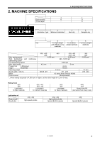
Brother International S-7200B Instruction Manual - English - Page 11
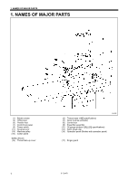
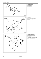
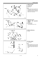
Table processing diagram, 3-2. Installation, Control box, Connecting rod
 |
View all Brother International S-7200B manuals
Add to My Manuals
Save this manual to your list of manuals |
Page 11 highlights
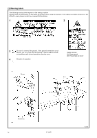
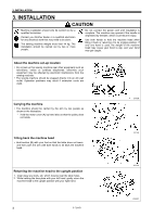
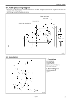
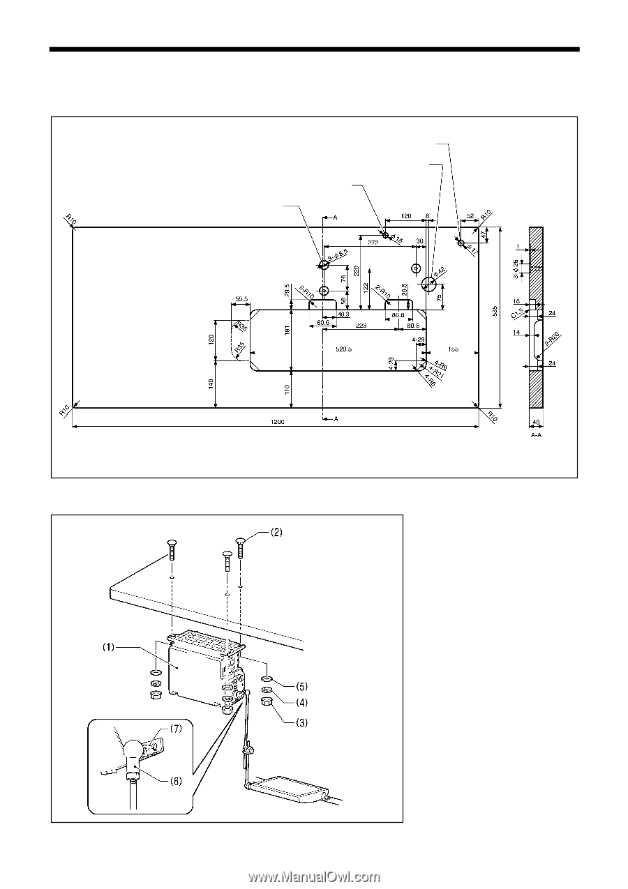
3. INSTALLATION 3-1. Table processing diagram The top of the table should be 40 mm in thickness and should be strong enough to hold the weight and with-stand the vibration of the sewing machine. Drill holes as indicated in the illustration below. Cotton stand hole Cord hole Head rest hole Control box mounting hole 3-2. Installation 2090M 1. Control box (1) Control box (2) Bolts [3 pcs] (3) Nuts [3 pcs] (4) Spring washers [3 pcs] (5) Washers [3 pcs] 2. Connecting rod (6) Connecting rod (7) Nut 2091M S-7200B 4
-
 1
1 -
2
-
3
-
4
-
5
-
 6
6 -
 7
7 -
 8
8 -
 9
9 -
 10
10 -
 11
11 -
 12
12 -
 13
13 -
 14
14 -
 15
15 -
 16
16 -
17
-
18
-
19
-
20
-
21
-
22
-
23
-
24
-
25
-
26
-
27
-
28
-
29
-
30
-
31
-
32
-
33
-
34
-
35
-
36
-
37
-
38
-
39
-
40
-
41
-
42
-
43
-
44
-
45
-
46
-
47
-
48
-
49
-
50
-
51
-
52
-
53
-
54
-
55
-
56
-
57
-
58
-
59
-
60
-
61
-
62
-
63
-
64
-
65
-
66
-
67
-
68
-
69
-
70
-
71
-
72
-
73
-
74
 |
 |
S-7200B
3. INSTALLATION
4
3-1. Table processing diagram
y
The top of the table should be 40 mm in thickness and should be strong enough to hold the weight and with-stand the
vibration of the sewing machine.
y
Drill holes as indicated in the illustration below.
3-2. Installation
1. Control box
(1) Control box
(2) Bolts [3 pcs]
(3) Nuts [3 pcs]
(4) Spring washers [3 pcs]
(5) Washers [3 pcs]
2. Connecting rod
(6) Connecting rod
(7) Nut
2090M
Cotton stand hole
Cord hole
Head rest hole
Control box mounting hole
2091M