Campbell Scientific 107 107-L Temperature Probe - Page 16
Operation
 |
View all Campbell Scientific 107 manuals
Add to My Manuals
Save this manual to your list of manuals |
Page 16 highlights
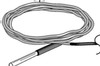
Model 107 Temperature Probe 8. Operation 8.1 Sensor Schematic FIGURE 8-1. 107 thermistor probe schematic 8.2 Measurement and Output Linearization Campbell Scientific dataloggers measure the 107 probe thermistor and convert the result to temperature. With reference to the previous FIGURE 8-1, 107 thermistor probe schematic, a precise excitation voltage is applied at the Vx line and the voltage drop across the 1 kΩ resistor is measured at the Vs line. The ratio of measured voltage (Vs) to excitation voltage (Vx) is related to thermistor resistance (Rs), and the 1 kΩ ohm and 249 kΩ fixed resistors as described in the following equations: Vs/Vx = 1000 / (Rs + 249000 Ω + 1000 Ω) Solving for Rs: Rs + 250000 Ω = 1000 • (Vx/Vs) Rs = 1000 • (Vx/Vs) - 249000 TABLE 8-1, 107 Measurement Details, and TABLE 8-2, 107 Temperature Calculation, describe how measurement results Vs/Vx and Rs are converted to temperature by Campbell Scientific dataloggers. 10
-
 1
1 -
2
-
3
-
4
-
5
-
6
-
7
-
8
-
9
-
10
-
 11
11 -
 12
12 -
 13
13 -
 14
14 -
 15
15 -
 16
16 -
 17
17 -
 18
18 -
 19
19 -
 20
20 -
 21
21 -
22
-
23
-
24
-
25
-
26
-
27
-
28
 |
 |
