Campbell Scientific AM16/32B AM16/32B Relay Multiplexer - Page 12
Physical Description
 |
View all Campbell Scientific AM16/32B manuals
Add to My Manuals
Save this manual to your list of manuals |
Page 12 highlights
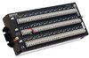
AM16/32B Relay Multiplexer NOTE For a discussion of single-ended versus differential analog measurements, please consult the measurement section of your datalogger manual. As purchased, the AM16/32B is intended for use in indoor, non-condensing environments. An enclosure is required for field or high humidity use. In applications where one or two multiplexers are deployed, the ENC10/12 (10" x 12") enclosure is recommended. 1.2 Compatibility The AM16/32B is compatible with Campbell's CR5000, CR800, CR850, CR3000, CR1000, CR23X, CR10(X), 21X, and CR7 dataloggers. The AM16/32B is compatible with a wide variety of commercially available sensors. As long as relay contact current maximums are not exceeded (see Cautionary Notes, page v), and no more than four lines are switched at a time, system compatibility for a specific sensor is determined by sensor-datalogger compatibility. In CR1000, CR800, CR850, CR3000, CR23X, and CR10(X) applications, the AM16/32B may be used to multiplex up to 16 Geokon vibrating wire sensors through one AVW1 vibrating wire interface. The AM16/32B can also be used to multiplex vibrating wire sensors connected to the AVW200 or AVW206. 2. Physical Description The AM16/32B is housed in a 10.2 x 23.9 x 4.6 cm (4.0 x 9.4 x 1.8 in) anodized aluminum case (FIGURE 2-1). The aluminum case is intended to reduce temperature gradients across the AM16/32B's terminal strips. An aluminum cover plate is also included to this end, and its use is extremely important if thermocouples are being multiplexed (Section 6.6, Thermocouple Measurement). The case can be opened for inspection/cleaning by removing two Phillips-head screws located on the underside of the case. Mounting tabs are provided so the AM16/32B can be fastened to a flat surface or an enclosure plate (Section 8, Installation). All connections to the AM16/32B are made on the top panel terminal blocks. The island of four terminals located near the mode switch are dedicated to the connecting of datalogger power and control lines (Section 4.1, The Control Terminals). The four ODD and EVEN COM terminals on the other side of the mode switch carry shielded multiplexed sensor signals destined for datalogger analog inputs. The remaining terminals on the AM16/32B are for sensor and sensor shield connection (Section 4.2, Measurement Terminals). All of the inputs of the AM16/32B are protected with gas tubes. The terminals accept stripped and tinned lead wires up to 16 AWG or 1.6 mm in diameter. Datalogger-to-AM16/32B cabling requires a minimum of six and as many as nine individually insulated wires with shields. 2
-
 1
1 -
2
-
3
-
4
-
5
-
6
-
 7
7 -
 8
8 -
 9
9 -
 10
10 -
 11
11 -
 12
12 -
 13
13 -
 14
14 -
 15
15 -
 16
16 -
 17
17 -
18
-
19
-
20
-
21
-
22
-
23
-
24
-
25
-
26
-
27
-
28
-
29
-
30
-
31
-
32
-
33
-
34
-
35
-
36
-
37
-
38
-
39
-
40
-
41
-
42
-
43
-
44
-
45
-
46
-
47
-
48
-
49
-
50
-
51
-
52
 |
 |
