Campbell Scientific AM16/32B AM16/32B Relay Multiplexer - Page 22
Datalogger P, rogramming
 |
View all Campbell Scientific AM16/32B manuals
Add to My Manuals
Save this manual to your list of manuals |
Page 22 highlights
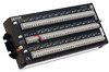
AM16/32B Relay Multiplexer (1H, 1L, 2H, 2L) are connected with COM (ODD H, ODD L, EVEN H, EVEN L) terminals respectively. When the second clock pulse is received, the first SET is switched out (channel 1 sensor inputs become open circuits) and SET 2 (3H, 3L, 4H, 4L) are connected to the four COM terminals. A given SET will typically be connected to the common terminals for 20 ms. With panel switch set to "2x32" mode, the white channel numbers apply. The SETs are labeled beginning with 1H, 1L and ending with 32H, 32L. In "2x32" mode when the AM16/32B selects a given channel, the "H" sensor terminal is relay connected to both COM "H" terminals and the "L" sensor terminal is connected to both COM "L" terminals (COM ODD H connects to COM EVEN H and COM ODD L connects to COM EVEN L when panel switch is in "2x32" mode). 5. Datalogger Programming SCWin Short Cut Program Builder for Windows can build many program configurations for various supported sensors providing a quick way to generate a program and wiring diagram (FIGURE 5-1). SCWin can be downloaded free of charge (www.campbellsci.com). FIGURE 5-1. SCWin (Short Cut for Windows program builder) 12
-
 1
1 -
2
-
3
-
4
-
5
-
6
-
7
-
8
-
9
-
10
-
11
-
12
-
13
-
14
-
15
-
16
-
 17
17 -
 18
18 -
 19
19 -
 20
20 -
 21
21 -
 22
22 -
 23
23 -
 24
24 -
 25
25 -
 26
26 -
 27
27 -
28
-
29
-
30
-
31
-
32
-
33
-
34
-
35
-
36
-
37
-
38
-
39
-
40
-
41
-
42
-
43
-
44
-
45
-
46
-
47
-
48
-
49
-
50
-
51
-
52
 |
 |
