Campbell Scientific TE525MM TE525, TE525WS, and TE525MM Texas Electronics Rain - Page 16
Datalogger Programming
 |
View all Campbell Scientific TE525MM manuals
Add to My Manuals
Save this manual to your list of manuals |
Page 16 highlights
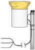
TE525 Tipping Bucket Rain Gage The CR10 does not support the use of control port inputs with the Pulse Count instruction. Black White Clear 100 Ω FIGURE 7-1. Rain Gage Schematic In a long cable, there is appreciable capacitance between the lines. A built up charge could cause arcing when the switch closes, shortening switch life. A 100 Ω resistor is connected in series at the switch to prevent arcing by limiting the current (FIGURE 7-1). This resistor is installed on all rain gages currently sold by Campbell Scientific. 7.2 Datalogger Programming This section is for users who write their own programs. A datalogger program to measure this sensor can be generated using Short Cut. You do not need to read this section to use Short Cut. In CRBasic, the rain gage is measured using the PulseCount() instruction. Choose switch closure (code 2) for the PConfig parameter. Dataloggers that use CRBasic are the CR200(X), CR800, CR850, CR1000, CR3000, CR5000, and CR9000(X). In Edlog, the Pulse (P3) is used to measure the rain gage. Choose switch closure (code 2) for parameter three. Dataloggers that use Edlog are the CR500, CR510, CR10(X), CR23X, CR7, and 21X. The multiplier used in the PulseCount() or Pulse (P3) instruction determines the units in which rainfall is reported (see TABLE 7-3). TABLE 7-3. Multipliers for Rain Measurement Rain Gage inches millimeters TE525 0.01 0.254 TE525WS 0.01 0.254 TE525MM 0.00394 0.1 TE525 or TE525MM w/8 in funnel 0.0057 0.1459 The volume of water required to cause a tip in the TE525 and the TE525MM is the same. The difference in calibration is strictly due to funnel size. If the CS705 Snowfall Adapter or other eight inch funnel is installed on these gages, use a multiplier from the last row in TABLE 7-3. (The CS705 will not install directly on the TE525MM; the MM funnel must first be replaced with an eight inch funnel.) 10
-
 1
1 -
2
-
3
-
4
-
5
-
6
-
7
-
8
-
9
-
10
-
 11
11 -
 12
12 -
 13
13 -
 14
14 -
 15
15 -
 16
16 -
 17
17 -
 18
18 -
 19
19 -
 20
20 -
 21
21 -
22
-
23
-
24
 |
 |
