Canon CanoScan N656U Service Manual
Canon CanoScan N656U Manual
 |
View all Canon CanoScan N656U manuals
Add to My Manuals
Save this manual to your list of manuals |
Canon CanoScan N656U manual content summary:
- Canon CanoScan N656U | Service Manual - Page 1
SERVICE MANUAL REVISION 0 JUNE 2000 COPYRIGHT © 2000 CANON INC. JY8-1317-00Z CANOSCAN N650U/N656U/N1220U REV.0 JUNE 2000 PRINTED IN JAPAN (IMPRIME AU JAPON) - Canon CanoScan N656U | Service Manual - Page 2
COPYRIGHT © 2000 CANON INC. Printed in Japan Imprimè au Japon Use of this manual should be strictly supervised to avoid disclosure of confidential information. COPYRIGHT © 2000 CANON INC. CANOSCAN N650U/N656U/N1220U REV.0 JUNE 2000 PRINTED IN JAPAN (IMPRIME AU JAPON) - Canon CanoScan N656U | Service Manual - Page 3
-4792-200 AZJ000001CZJ000001DZJ000001FZJ000001LZJ000001JZJ000001KZJ000001AZK000001MZK000001CZK000001DZK000001FZK000001LZK000001JZK000001KZK000001AZL000001MZL000001CZL000001DZL000001FZL000001LZL000001JZL000001KZL000001- COPYRIGHT © 2000 CANON INC. CANOSCAN N650U/N656U/N1220U REV.0 JUNE 2000 PRINTED - Canon CanoScan N656U | Service Manual - Page 4
and lubricants Chapter 5: Troubleshooting Introduction, troubleshooting, location of electrical parts, canon scanner test Chapter 6: Parts Catalog Appendix: General Circuit Diagram, Main PCB Circuit Diagram, USB Connector PCB Circuit Diagram The information in this service manual is subject to - Canon CanoScan N656U | Service Manual - Page 5
Front View 1-4 B. Rear View 1-4 IV. INSTALLATION 1-5 A. Preface 1-5 B. Installation 1-6 C. Connecting to the Host Computer 1-7 3-9 IV. ELECTRICAL SYSTEM 3-11 A. USB Connector PCB 3-11 B. Flat Cable 3-13 COPYRIGHT © 2000 CANON INC. CANOSCAN N650U/N656U/N1220U REV.0 JUNE 2000 PRINTED IN - Canon CanoScan N656U | Service Manual - Page 6
Image Defects 5-2 B. Troubleshooting Malfunctions 5-3 III. LOCATION OF ELECTRICAL PARTS 5-4 IV. CANON SCANNER TEST 5-5 A. Outline 5-5 B. How To Use Canon Scanner Test 5-5 CHAPTER 6 : PARTS CATALOG FIGURE U01 ACCESSORY ......... 6-2 FIGURE U10 N650U 6-4 FIGURE U11 N656U 6-6 FIGURE U20 - Canon CanoScan N656U | Service Manual - Page 7
Front View 1-4 B. Rear View 1-4 IV. INSTALLATION 1-5 A. Preface 1-5 B. Installation 1-6 C. Connecting to the Host Computer 1-7 D. Scanning a Document .......... 1-8 V. CUSTOMER'S DAILY MAINTENANCE 1-9 COPYRIGHT © 2000 CANON INC. CANOSCAN N650U/N656U/N1220U REV.0 JUNE 2000 PRINTED IN JAPAN - Canon CanoScan N656U | Service Manual - Page 8
document cover to hold a thick document. 5. The scanner can be placed vertically to scan by using an optional stand. 6. The scanner draws its power from USB port on the host computer requiring no AC adapter. COPYRIGHT © 2000 CANON INC. CANOSCAN N650U/N656U/N1220U REV.0 JUNE 2000 PRINTED IN JAPAN - Canon CanoScan N656U | Service Manual - Page 9
600 dpi) 16 sec. (preview) : USB 1.1 (B plug) x 1 : Temperature range, 5 to 35˚C Humidity range, 10 to 90% Air pressure range, 613 to 1013 hPa : 2.5W (during operation) : 256.0(W) x 372.5(D) x 34.0(H) mm : 1.4 kg 1 - 2 COPYRIGHT © 2000 CANON INC. CANOSCAN N650U/N656U/N1220U REV.0 JUNE 2000 PRINTED - Canon CanoScan N656U | Service Manual - Page 10
: USB 1.1 (B plug) x 1 : Temperature range, 5 to 35˚C Humidity range, 10 to 90% Air pressure range, 613 to 1013 hPa : 2.5W (during operation) : 256.0(W) x 372.5(D) x 34.0(H) mm : 1.4 kg Specifications are subject to change with product improvement. COPYRIGHT © 2000 CANON INC. CANOSCAN N650U/N656U - Canon CanoScan N656U | Service Manual - Page 11
A. Front View 1 3 q Document Cover w Document Glass e Alignment Mark r Start Button t Carriage Lock 4 B. Rear View A4 2 LTR B5 B5 A4 LTR 5 Figure 1-1 q USB Port 1 Figure 1-2 1 - 4 COPYRIGHT © 2000 CANON INC. CANOSCAN N650U/N656U/N1220U REV.0 JUNE 2000 PRINTED IN JAPAN (IMPRIME AU JAPON) - Canon CanoScan N656U | Service Manual - Page 12
place to a warm place can cause condensation on the metal parts, resulting in a faulty operation. Give the scanner at least one hour to adjust to the room temperature before unpacking. COPYRIGHT © 2000 CANON INC. CANOSCAN N650U/N656U/N1220U REV.0 JUNE 2000 PRINTED IN JAPAN (IMPRIME AU JAPON) 1 - 5 - Canon CanoScan N656U | Service Manual - Page 13
the carriage lock to the unlock mark position. 1 q Carriage Lock Figure 1-4 3) Return the scanner to its standard position. Note: Always lock the scanning unit during transport. 1 - 6 COPYRIGHT © 2000 CANON INC. CANOSCAN N650U/N656U/N1220U REV.0 JUNE 2000 PRINTED IN JAPAN (IMPRIME AU JAPON) - Canon CanoScan N656U | Service Manual - Page 14
the flat connector (A plug) of the USB cable to the USB port on the host computer. 2) Connect the square connector (B plug) of the USB cable to the USB port on the scanner. q USB Port w USB Cable 1 2 Figure 1-5 COPYRIGHT © 2000 CANON INC. CANOSCAN N650U/N656U/N1220U REV.0 JUNE 2000 PRINTED IN - Canon CanoScan N656U | Service Manual - Page 15
q Alignment Mark Figure 1-6 3) Close the document cover, caring not to dislodge the document. 4) Send the "SCAN" command from the host computer to scan. 1 - 8 COPYRIGHT © 2000 CANON INC. CANOSCAN N650U/N656U/N1220U REV.0 JUNE 2000 PRINTED IN JAPAN (IMPRIME AU JAPON) - Canon CanoScan N656U | Service Manual - Page 16
the scanner. 2) Wipe the dirt or dust off the document cover with a soft clean cloth dampened with water and well wrung, then thoroughly wipe water off with a dry cloth. 3) Wipe the document glass with a dry cloth caring not to leave wiper marks. COPYRIGHT © 2000 CANON INC. CANOSCAN N650U/N656U - Canon CanoScan N656U | Service Manual - Page 17
Circuit 2-16 III. IMAGE PROCESSING SYSTEM . 2-17 A. Outline 2-17 B. Image Processing Functions 2-18 IV. CONTROL SYSTEM 2-20 A. Outline 2-20 B. Outline of USB 2-21 V. POWER SUPPLY 2-23 COPYRIGHT © 2000 CANON INC. CANOSCAN N650U/N656U/N1220U REV.0 JUNE 2000 PRINTED IN JAPAN (IMPRIME AU JAPON) - Canon CanoScan N656U | Service Manual - Page 18
The scanner functions are divided into the three main blocks of optical system, image processing system, and control system. Host computer Contact image sensor Drive motor Optical system Control system Image processing system Figure 2-1 COPYRIGHT © 2000 CANON INC. CANOSCAN N650U/N656U/N1220U - Canon CanoScan N656U | Service Manual - Page 19
equipped in the main PCB. The device driver installed in the host computer includes a control program USB Connector PCB J2 Main PCB J1 Buffer RAM Host computer Control program Start button Gate array S1 Home position sensor Q4 Figure 2-2 2 - 2 COPYRIGHT © 2000 CANON INC. CANOSCAN N650U/N656U - Canon CanoScan N656U | Service Manual - Page 20
C. Main PCB Input and Output CHAPTER 2 To host computer USB connector PCB J1-1 Vbus -2 D-3 D+ -4 GND J2-1 -2 10 BEN -11 GEN -12 REN GND HPSEN "H" when scanning unit is in home position GND SCANSW "L" when start button was pressed GND Figure 2-3 COPYRIGHT © 2000 CANON INC. CANOSCAN N650U/N656U - Canon CanoScan N656U | Service Manual - Page 21
CHAPTER 2 D. Basic Sequences The basic sequences of the scanner are divided into power ON sequence, calibration sequence, and Sets error flag Stops scanning unit 1 Figure 2-4-1 2 - 4 COPYRIGHT © 2000 CANON INC. CANOSCAN N650U/N656U/N1220U REV.0 JUNE 2000 PRINTED IN JAPAN (IMPRIME AU JAPON) - Canon CanoScan N656U | Service Manual - Page 22
? YES Sets error flag Detects white mark area White mark area NO was detected normally? YES Sets error flag LED OFF Standby Figure 2-4-2 COPYRIGHT © 2000 CANON INC. CANOSCAN N650U/N656U/N1220U REV.0 JUNE 2000 PRINTED IN JAPAN (IMPRIME AU JAPON) 2 - 5 - Canon CanoScan N656U | Service Manual - Page 23
/Border detection between black and white The scanner detects the home position by the home position sensor by using a black mark area and white mark completed, the scanner is on standby to wait for a command from the host computer. 2 - 6 COPYRIGHT © 2000 CANON INC. CANOSCAN N650U/N656U/N1220U REV - Canon CanoScan N656U | Service Manual - Page 24
data Sets black calibration data to gate array Black calibration data was NO set to gate array normally? YES 2 Sets error flag Figure 2-6-1 COPYRIGHT © 2000 CANON INC. CANOSCAN N650U/N656U/N1220U REV.0 JUNE 2000 PRINTED IN JAPAN (IMPRIME AU JAPON) 2 - 7 - Canon CanoScan N656U | Service Manual - Page 25
error flag Composes white calibration data LED OFF Moves scanning unit to the home position Stores white calibration data as a file Standby Figure 2-6-2 2 - 8 COPYRIGHT © 2000 CANON INC. CANOSCAN N650U/N656U/N1220U REV.0 JUNE 2000 PRINTED IN JAPAN (IMPRIME AU JAPON) - Canon CanoScan N656U | Service Manual - Page 26
2 When the host computer sends a calibration command, the scanner performs the calibration. Calibration is to compose black calibration data 600/300 dpi, only green data is processed. COPYRIGHT © 2000 CANON INC. CANOSCAN N650U/N656U/N1220U REV.0 JUNE 2000 PRINTED IN JAPAN (IMPRIME AU JAPON) 2 - 9 - Canon CanoScan N656U | Service Manual - Page 27
LED OFF Returns scanning unit Scanning unit returned NO to the home position? YES Stops drive motor Image data NO was transmitted? YES Standby Figure 2-7 2 - 10 COPYRIGHT © 2000 CANON INC. CANOSCAN N650U/N656U/N1220U REV.0 JUNE 2000 PRINTED IN JAPAN (IMPRIME AU JAPON) - Canon CanoScan N656U | Service Manual - Page 28
drives the scanning unit via the drive pulley and drive wire. Contact image sensor Sliding rod Drive pulley Drive motor Drive wire Figure 2-8 COPYRIGHT © 2000 CANON INC. CANOSCAN N650U/N656U/N1220U REV.0 JUNE 2000 PRINTED IN JAPAN (IMPRIME AU JAPON) 2 - 11 - Canon CanoScan N656U | Service Manual - Page 29
To maintain the scanner is completed until the ready for scan. scanner receives a scan command from the host computer. HPDET After the scanner received a To scan. Table 2-1 2 - 12 COPYRIGHT © 2000 CANON INC. CANOSCAN N650U/N656U/N1220U REV.0 JUNE 2000 PRINTED IN JAPAN (IMPRIME AU JAPON) - Canon CanoScan N656U | Service Manual - Page 30
exposes a document through the light conductor section. This is called LIDE (LED Indirect Exposure). The light reflected from the document is collected conductor section LED Phototransistor array Figure 2-10 COPYRIGHT © 2000 CANON INC. CANOSCAN N650U/N656U/N1220U REV.0 JUNE 2000 PRINTED IN JAPAN (IMPRIME - Canon CanoScan N656U | Service Manual - Page 31
signal Image signal output Sensor drive circuit Phototransistor array R GB LED Phototransistor array Phototransistor array Phototransistor array Rod lens array Figure 2-12 2 - 14 COPYRIGHT © 2000 CANON INC. CANOSCAN N650U/N656U/N1220U REV.0 JUNE 2000 PRINTED IN JAPAN (IMPRIME AU JAPON) - Canon CanoScan N656U | Service Manual - Page 32
LED is ON and the image signal is processed. SP RLED GLED BLED 5.16ms 5.16ms 5.16ms Image signal output R GBR GBR Figure 2-13 COPYRIGHT © 2000 CANON INC. CANOSCAN N650U/N656U/N1220U REV.0 JUNE 2000 PRINTED IN JAPAN (IMPRIME AU JAPON) 2 - 15 - Canon CanoScan N656U | Service Manual - Page 33
the rotating speed of the drive motor. Host computer Control program Main PCB Gate array MA+ MBMB+ MA- Motor driver PA+ J2-1 PB- -2 PB+ -3 PA- -4 Drive motor M1 Figure 2-14 2 - 16 COPYRIGHT © 2000 CANON INC. CANOSCAN N650U/N656U/N1220U REV.0 JUNE 2000 PRINTED IN JAPAN (IMPRIME AU JAPON) - Canon CanoScan N656U | Service Manual - Page 34
outputs the data to the host computer via USB port. 1. Contact image sensor 2. A/D conversion 3. Resolution conversion 4. Calibration 5. Gamma correction 6. Packing To host computer Figure 2-15 COPYRIGHT © 2000 CANON INC. CANOSCAN N650U/N656U/N1220U REV.0 JUNE 2000 PRINTED IN JAPAN (IMPRIME - Canon CanoScan N656U | Service Manual - Page 35
output from the contact image sensor are converted into the digital image data of 14 bits each by A/D converter in the gate array in order of red image signal, green unit Figure 2-18 2 - 18 COPYRIGHT © 2000 CANON INC. CANOSCAN N650U/N656U/N1220U REV.0 JUNE 2000 PRINTED IN JAPAN (IMPRIME AU JAPON) - Canon CanoScan N656U | Service Manual - Page 36
are corrected by the calibration. Calibration data is used as standard density data when scanning a document image data input to the buffer RAM is converted to 8 bits by the gamma curve data and is output. 6. Packing © 2000 CANON INC. CANOSCAN N650U/N656U/N1220U REV.0 JUNE 2000 PRINTED IN JAPAN (IMPRIME AU - Canon CanoScan N656U | Service Manual - Page 37
is used as a work memory for image processing. The scanner communicates with the host computer via USB interface in the gate array. Host computer Control program gate array USB I/F A0-7 D0-15 Buffer RAM ROM Control signal Figure 2-21 2 - 20 COPYRIGHT © 2000 CANON INC. CANOSCAN N650U/N656U - Canon CanoScan N656U | Service Manual - Page 38
up to 6 layers. 3) USB cable must be 5 meters or shorter. Layer 1 Layer 2 Layer 3 Layer 4 Layer 5 Layer 6 Host computer Hub 1 Node Hub 2 Node Hub 3 Hub 6 Hub 4 Node Hub 5 Node Node Node Node Node Node Figure 2-22 COPYRIGHT © 2000 CANON INC. CANOSCAN N650U/N656U/N1220U REV.0 JUNE - Canon CanoScan N656U | Service Manual - Page 39
host computer when USB device is attached/ removed. 4) Bulk transfer : Lowest priority is given but larger amounts of data is sequentially transferred to a free bus. This scanner uses control transfer and bulk transfer. 2 - 22 COPYRIGHT © 2000 CANON INC. CANOSCAN N650U/N656U/N1220U REV.0 JUNE - Canon CanoScan N656U | Service Manual - Page 40
is used for the analog circuit and for driving the contact image sensor. Host comuter USB +5V port Main PCB 5.5V step up circuit Gate array 5.0V reference voltage Analog circuit Digital circuit Drive motor LED Contact image sensor Figure 2-24 COPYRIGHT © 2000 CANON INC. CANOSCAN N650U/N656U - Canon CanoScan N656U | Service Manual - Page 41
SYSTEM 3-5 A. Drive Unit 3-5 B. Drive Wire 3-8 III. OPTICAL SYSTEM 3-9 A. Contact Image Sensor ......... 3-9 IV. ELECTRICAL SYSTEM 3-11 A. USB Connector PCB 3-11 B. Flat Cable 3-13 COPYRIGHT © 2000 CANON INC. CANOSCAN N650U/N656U/N1220U REV.0 JUNE 2000 PRINTED IN JAPAN (IMPRIME AU JAPON) - Canon CanoScan N656U | Service Manual - Page 42
cleaning, checking or repairing inside the scanner, remove the necessary covers using the following procedures. A. Covers 1 A4 LTR 2 B5 3 B5 A4 LTR q Document Cover w Document Glass Unit e Base Frame Figure 3-1 COPYRIGHT © 2000 CANON INC. CANOSCAN N650U/N656U/N1220U REV.0 JUNE 2000 PRINTED - Canon CanoScan N656U | Service Manual - Page 43
left, remove the right hinge unit, then warp the document cover to remove. 3 A4 LTR B5 1 2 1 2 B5 A4 LTR q Document Cover w Hinge Figure 3-2 3 - 2 COPYRIGHT © 2000 CANON INC. CANOSCAN N650U/N656U/N1220U REV.0 JUNE 2000 PRINTED IN JAPAN (IMPRIME AU JAPON) - Canon CanoScan N656U | Service Manual - Page 44
Glass Unit Figure 3-3 Note: Do not lift the hook part excessively since it is attached to the document glass with a double-sided tape. COPYRIGHT © 2000 CANON INC. CANOSCAN N650U/N656U/N1220U REV.0 JUNE 2000 PRINTED IN JAPAN (IMPRIME AU JAPON) 3 - 3 - Canon CanoScan N656U | Service Manual - Page 45
B5 A4 LTR Figure 3-5 Note: Take care not to smear the rear side of the document glass unit (especially the spacer sliding surface). 3 - 4 COPYRIGHT © 2000 CANON INC. CANOSCAN N650U/N656U/N1220U REV.0 JUNE 2000 PRINTED IN JAPAN (IMPRIME AU JAPON) - Canon CanoScan N656U | Service Manual - Page 46
the seal from the back of the scanner, push the wire stopper backward to remove it from the base frame through the left hole. 1 2 q Wire Stopper w Seal Figure 3-6 Note: Do not damage or lose the seal to reuse it. COPYRIGHT © 2000 CANON INC. CANOSCAN N650U/N656U/N1220U REV.0 JUNE 2000 PRINTED IN - Canon CanoScan N656U | Service Manual - Page 47
, then disconnect the connector J3. 1 q Connector J3 Figure 3-8 7) Remove the contact image sensor (refer to III-A-1). 8) Lift the drive unit to remove it. 3 - 6 COPYRIGHT © 2000 CANON INC. CANOSCAN N650U/N656U/N1220U REV.0 JUNE 2000 PRINTED IN JAPAN (IMPRIME AU JAPON) - Canon CanoScan N656U | Service Manual - Page 48
unit 1) Apply appropriate amount of grease to the positions marked with net in the figure 3-9. Figure 3-9 2) Locate the drive wire referring to II-B-2. COPYRIGHT © 2000 CANON INC. CANOSCAN N650U/N656U/N1220U REV.0 JUNE 2000 PRINTED IN JAPAN (IMPRIME AU JAPON) 3 - 7 - Canon CanoScan N656U | Service Manual - Page 49
3-10 2. Precautions when attaching the drive wire 1) When the drive wire is twisted, untwist it to a natural condition. Otherwise a twisted drive wire can affect an image. 2) Locate the drive wire as shown in Figure 3-11. Figure 3-11 3 - 8 COPYRIGHT © 2000 CANON INC. CANOSCAN N650U/N656U/N1220U - Canon CanoScan N656U | Service Manual - Page 50
2) Remove the document glass unit. 3) Remove the seal from the back of the scanner unit, push the wire stopper backward to remove it from the base frame through the . 2 1 Figure 3-12 COPYRIGHT © 2000 CANON INC. CANOSCAN N650U/N656U/N1220U REV.0 JUNE 2000 PRINTED IN JAPAN (IMPRIME AU JAPON) 3 - 9 - Canon CanoScan N656U | Service Manual - Page 51
, then remove the contact image sensor. 1 2 3 q Contact Image Sensor w Sensor Cable e Spring Figure 3-13 Note: Do not lose the spring under the contact image sensor. 3 - 10 COPYRIGHT © 2000 CANON INC. CANOSCAN N650U/N656U/N1220U REV.0 JUNE 2000 PRINTED IN JAPAN (IMPRIME AU JAPON) - Canon CanoScan N656U | Service Manual - Page 52
glass unit. 3) Insert flat-blade screw drivers into both sides of the USB connector PCB to push it forward. Figure 3-14 4) Disconnect the connector J2 to remove the USB connector PCB. 1 q Connector J2 Figure 3-15 COPYRIGHT © 2000 CANON INC. CANOSCAN N650U/N656U/N1220U REV.0 JUNE 2000 PRINTED IN - Canon CanoScan N656U | Service Manual - Page 53
CHAPTER 3 2. Precautions when attaching the USB connector PCB 1) Make sure to contact the ground of the USB connector PCB with the sliding rod. 1 2 q Ground w Sliding Rod Figure 3-16 3 - 12 COPYRIGHT © 2000 CANON INC. CANOSCAN N650U/N656U/N1220U REV.0 JUNE 2000 PRINTED IN JAPAN (IMPRIME AU - Canon CanoScan N656U | Service Manual - Page 54
3) Remove the seal from the back of the scanner unit, push the wire stopper backward to remove it USB connector PCB, and disconnect the connector J2. 8) Pull to remove the flat cable from the ferrite core. 2 1 q Flat Cable w Ferrite Core Figure 3-17 COPYRIGHT © 2000 CANON INC. CANOSCAN N650U/N656U - Canon CanoScan N656U | Service Manual - Page 55
2) Locate the flat cable as follows. a. The flat cable on the USB connector PCB side is attached with a double-sided tape. Align the bend flat cable on the driver unit side and pass it through the ferrite core. Figure 3-19 3 - 14 COPYRIGHT © 2000 CANON INC. CANOSCAN N650U/N656U/N1220U REV.0 JUNE - Canon CanoScan N656U | Service Manual - Page 56
CHAPTER 3 3) Re-bend the flat cable as shown in Figure 3-20 and connect it to the connector J3. 8mm Figure 3-20 1 q Connector J3 Figure 3-21 COPYRIGHT © 2000 CANON INC. CANOSCAN N650U/N656U/N1220U REV.0 JUNE 2000 PRINTED IN JAPAN (IMPRIME AU JAPON) 3 - 15 - Canon CanoScan N656U | Service Manual - Page 57
CHAPTER 4 MAINTENANCE AND SERVICING I. PERIODICAL REPLACEMENT PARTS 4-1 II. CONSUMABLE PARTS DURABILITY 4-1 III. PERIODICAL SERVICING .......... 4-1 IV. SPECIAL TOOLS 4-1 V. SOLVENTS AND LUBRICANTS ... 4-1 COPYRIGHT © 2000 CANON INC. CANOSCAN N650U/N656U/N1220U REV.0 JUNE 2000 PRINTED IN JAPAN - Canon CanoScan N656U | Service Manual - Page 58
AND LUBRICANTS Lubricants used for disassembly and assembly of the scanner. No. Name 1 Grease Tool No. Usage / Remarks TKC-0955 To be applied to the sliding part between the scanning unit and sliding rod. MOLYKOTE EM-50L Table 4-1 COPYRIGHT © 2000 CANON INC. CANOSCAN N650U/N656U/N1220U REV - Canon CanoScan N656U | Service Manual - Page 59
B. Others 5-1 II. TROUBLESHOOTING 5-2 A. Troubleshooting Image Defects 5-2 B. Troubleshooting Malfunctions 5-3 III. LOCATION OF ELECTRICAL PARTS 5-4 IV. CANON SCANNER TEST 5-5 A. Outline 5-5 B. How To Use Canon Scanner Test 5-5 COPYRIGHT © 2000 CANON INC. CANOSCAN N650U/N656U/N1220U REV - Canon CanoScan N656U | Service Manual - Page 60
a window, hang a curtain to block direct sunlight. 5. The scanner is installed in a well-ventilated place. B. Others Moving a scanner from a cold place to a warm place can cause condensation on the metal parts, resulting in a faulty operation. COPYRIGHT © 2000 CANON INC. CANOSCAN N650U/N656U/N1220U - Canon CanoScan N656U | Service Manual - Page 61
Troubleshooting Image Defects 1. Image not output Cause 1 : Faulty connection of the USB cable Corrective action : Securely connect the USB light is entering into the scanner. External light entering into the - 2 COPYRIGHT © 2000 CANON INC. CANOSCAN N650U/N656U/N1220U REV.0 JUNE 2000 PRINTED - Canon CanoScan N656U | Service Manual - Page 62
5 B. Troubleshooting Malfunctions 1. Host computer not detecting the scanner Cause 1 : Faulty installation of the device driver Corrective action : Uninstall the device driver and reinstall it. Cause 2 : Faulty connection of the USB cable Corrective action : Securely connect the USB cable to - Canon CanoScan N656U | Service Manual - Page 63
CHAPTER 5 III. LOCATION OF ELECTRICAL PARTS 1 2 3 4 5 q USB Connector PCB w Main PCB e Contact Image Sensor r Home Position Sensor t Start Button y Drive Motor 6 Figure 5-1 5 - 4 COPYRIGHT © 2000 CANON INC. CANOSCAN N650U/N656U/N1220U REV.0 JUNE 2000 PRINTED IN JAPAN (IMPRIME AU JAPON) - Canon CanoScan N656U | Service Manual - Page 64
Windows 98 Operating System 4) Scanner Device Driver Macintosh platform 1) CanoScan N650U/N656U/N1220U 2) Power Macintosh 3) Macintosh OS (Version 8.5 or later) 4) Scanner Device Driver Note: Install the scanner device driver before using the Canon Scanner Test. COPYRIGHT © 2000 CANON INC. CANOSCAN - Canon CanoScan N656U | Service Manual - Page 65
the host computer. 3) Scanner Self Test Scanner self test is performed. 4) Calibration Scanner calibration is performed. 5) Scan Any image is scanned and saved as an image file in the same folder with the Canon Scanner Test. 5 - 6 COPYRIGHT © 2000 CANON INC. CANOSCAN N650U/N656U/N1220U REV.0 JUNE - Canon CanoScan N656U | Service Manual - Page 66
Name · Local Name Figure 5-2 : Manufacturer name (Canon) of the scanner connected. : Product name of the scanner connected. : Port name of the scanner recognized by Windows. : Product name of the scanner connected. COPYRIGHT © 2000 CANON INC. CANOSCAN N650U/N656U/N1220U REV.0 JUNE 2000 PRINTED IN - Canon CanoScan N656U | Service Manual - Page 67
5-3 (Windows) or Figure 5-4 (Macintosh). Figure 5-3 Figure 5-4 · Vendor ID · Product ID · ROM Version : Manufacturer name (Canon) of the scanner connected. : Product name of the scanner connected. : Scanner controller version. 5 - 8 COPYRIGHT © 2000 CANON INC. CANOSCAN N650U/N656U/N1220U REV - Canon CanoScan N656U | Service Manual - Page 68
CHAPTER 5 3) Scanner Self Test Select "Scanner Self Test" from the "Function" menu to display a dialog as shown in Figure 5-5 (Windows) or Figure 5-6 (Macintosh). Figure 5-5 Figure 5-6 COPYRIGHT © 2000 CANON INC. CANOSCAN N650U/N656U/N1220U REV.0 JUNE 2000 PRINTED IN JAPAN (IMPRIME AU JAPON) 5 - - Canon CanoScan N656U | Service Manual - Page 69
CHAPTER 5 Click "OK" to perform Scanner Self Test. When it has completed normally, a dialog as shown in Figure 5-7 (Window) or Figure 5-8 (Macintosh) is displayed. Figure 5-7 Figure 5-8 5 - 10 COPYRIGHT © 2000 CANON INC. CANOSCAN N650U/N656U/N1220U REV.0 JUNE 2000 PRINTED IN JAPAN (IMPRIME AU - Canon CanoScan N656U | Service Manual - Page 70
CHAPTER 5 4) Calibration Select "Calibration" from the "Function" menu to display a dialog as shown in Figure 5-9 (Windows) or 5-10 (Macintosh). Figure 5-9 Figure 5-10 COPYRIGHT © 2000 CANON INC. CANOSCAN N650U/N656U/N1220U REV.0 JUNE 2000 PRINTED IN JAPAN (IMPRIME AU JAPON) 5 - 11 - Canon CanoScan N656U | Service Manual - Page 71
5 Click "OK" to perform Calibration. When it has completed normally, a dialog as shown in Figure 5-11 (Windows) or Figure 5-12 (Macintosh) is displayed. Figure 5-11 Figure 5-12 5 - 12 COPYRIGHT © 2000 CANON INC. CANOSCAN N650U/N656U/N1220U REV.0 JUNE 2000 PRINTED IN JAPAN (IMPRIME AU JAPON) - Canon CanoScan N656U | Service Manual - Page 72
CHAPTER 5 5) Scan Select "Scan" from the "Function" menu to display a dialog as shown in Figure 5-13 (Windows) or Figure 5-14 (Macintosh). Figure 5-13 COPYRIGHT © 2000 CANON INC. CANOSCAN N650U/N656U/N1220U REV.0 JUNE 2000 PRINTED IN JAPAN (IMPRIME AU JAPON) 5 - 13 - Canon CanoScan N656U | Service Manual - Page 73
MByte 1200 dpi : Approx. 15.0 MByte Note: Confirm before scanning that the available disk space on the HDD in which the Canon Scanner Test is installed exceeds above file capacity. 5 - 14 COPYRIGHT © 2000 CANON INC. CANOSCAN N650U/N656U/N1220U REV.0 JUNE 2000 PRINTED IN JAPAN (IMPRIME AU JAPON) - Canon CanoScan N656U | Service Manual - Page 74
may occur during Canon Scanner Test are described below. 1) When Canon Scanner Test is started, "Unable to find USB scanner" is displayed. Cause 1 : Device driver for the scanner is not installed in the host computer. Corrective action : Install the device driver. Cause 2 : Scanner is not - Canon CanoScan N656U | Service Manual - Page 75
CHAPTER 6 PARTS CATALOG FIGURE U01 ACCESSORY ......... 6-2 FIGURE U10 N650U 6-4 FIGURE U11 N656U 6-6 FIGURE U20 N1220U 6-8 COPYRIGHT © 2000 CANON INC. CANOSCAN N650U/N656U/N1220U REV.0 JUNE 2000 PRINTED IN JAPAN (IMPRIME AU JAPON) - Canon CanoScan N656U | Service Manual - Page 76
(Brank Page) COPYRIGHT © 2000 CANON INC. CANOSCAN N650U/N656U/N1220U REV.0 JUNE 2000 PRINTED IN JAPAN (IMPRIME AU JAPON) 6 - 1 - Canon CanoScan N656U | Service Manual - Page 77
FIGURE U01 ACCESSORY 1 2 3 6 - 2 COPYRIGHT © 2000 CANON INC. CANOSCAN N650U/N656U/N1220U REV.0 JUNE 2000 PRINTED IN JAPAN (IMPRIME AU JAPON) - Canon CanoScan N656U | Service Manual - Page 78
FIGURE & KEY NO. U01-01 02 03 R Q' PART NUMBER A N T KY DESCRIPTION 104-0138-0SP 1 CABLE, USB 002-0827-0SP 1 STAND ASSEMBLY 003-7204-0SP 1 TAPE SERIAL NUMBER/REMARKS COPYRIGHT © 2000 CANON INC. CANOSCAN N650U/N656U/N1220U REV.0 JUNE 2000 PRINTED IN JAPAN (IMPRIME AU JAPON) 6 - 3 - Canon CanoScan N656U | Service Manual - Page 79
FIGURE U10 1 N650U A4 LTR B5 2 3 4 B 5 A4 5 LTR 6 7 9 10 15 11 12 13 14 8 16 17 18 6 - 4 COPYRIGHT © 2000 CANON INC. CANOSCAN N650U/N656U/N1220U REV.0 JUNE 2000 PRINTED IN JAPAN (IMPRIME AU JAPON) - Canon CanoScan N656U | Service Manual - Page 80
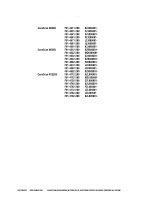
& KEY NO. U10-01 02 03 04 05 06 07 08 09 10 11 12 13 14 15 16 17 18 R Q' PART NUMBER A N 004-0393-000 1 USB I/F PCB ASSEMBLY 084-5505-0SP 1 SEAL NPN 1 BASE FRAME 051-0574-000 1 LOCK, CARRIAGE SERIAL NUMBER/REMARKS COPYRIGHT © 2000 CANON INC. CANOSCAN N650U/N656U/N1220U REV.0 JUNE 2000 - Canon CanoScan N656U | Service Manual - Page 81
FIGURE U11 1 N656U A4 LTR B5 2 3 4 B5 5 A4 LTR 6 7 9 10 15 11 12 13 14 8 16 17 18 6 - 6 COPYRIGHT © 2000 CANON INC. CANOSCAN N650U/N656U/N1220U REV.0 JUNE 2000 PRINTED IN JAPAN (IMPRIME AU JAPON) - Canon CanoScan N656U | Service Manual - Page 82
& KEY NO. U11-01 02 03 04 05 06 07 08 09 10 11 12 13 14 15 16 17 18 R Q' PART NUMBER A N 004-0393-000 1 USB I/F PCB ASSEMBLY 084-5509-0SP 1 SEAL NPN 1 BASE FRAME 051-0620-000 1 LOCK, CARRIAGE SERIAL NUMBER/REMARKS COPYRIGHT © 2000 CANON INC. CANOSCAN N650U/N656U/N1220U REV.0 JUNE 2000 - Canon CanoScan N656U | Service Manual - Page 83
FIGURE U20 1 N1220U A4 LTR B5 2 3 4 B5 A4 5 LTR 6 7 9 10 15 11 12 13 14 8 16 17 18 6 - 8 COPYRIGHT © 2000 CANON INC. CANOSCAN N650U/N656U/N1220U REV.0 JUNE 2000 PRINTED IN JAPAN (IMPRIME AU JAPON) - Canon CanoScan N656U | Service Manual - Page 84
& KEY NO. U20-01 02 03 04 05 06 07 08 09 10 11 12 13 14 15 16 17 18 R Q' PART NUMBER A N 004-0393-000 1 USB I/F PCB ASSEMBLY 084-5506-0SP 1 SEAL NPN 1 BASE FRAME 051-0617-000 1 LOCK, CARRIAGE SERIAL NUMBER/REMARKS COPYRIGHT © 2000 CANON INC. CANOSCAN N650U/N656U/N1220U REV.0 JUNE 2000 - Canon CanoScan N656U | Service Manual - Page 85
CIRCUIT DIAGRAM (CanoScan N650U/N656U) ......... A-3 IV. USB CONNECTOR PCB CIRCUIT DIAGRAM (CanoScan N650U/N656U A-6 V. MAIN PCB CIRCUIT DIAGRAM (CanoScan N1220U A-7 VI. USB CONNECTOR PCB CIRCUIT DIAGRAM (CanoScan N1220U) . A-10 COPYRIGHT © 2000 CANON INC. CANOSCAN N650U/N656U/N1220U REV.0 JUNE - Canon CanoScan N656U | Service Manual - Page 86
A - 1 COPYRIGHT © 2000 CANON INC. CANOSCAN N650U/N656U/N1220U REV.0 JUNE 2000 PRINTED IN JAPAN (IMPRIME AU JAPON) CS1 1 2 3 4 5 6 7 8 9 10 11 12 Contact Image Sensor Main PCB Q4 Home Position Sensor S1 Start Button J3 1 VOB 2 MISC6 3 GND 4 VCIS 5 VREF 6 TR 7 PHI1 8 VLED 9 BEN 10 GEN 11 REN 12 - Canon CanoScan N656U | Service Manual - Page 87
COPYRIGHT © 2000 CANON INC. CANOSCAN N650U/N656U/N1220U REV.0 JUNE 2000 PRINTED IN JAPAN (IMPRIME AU JAPON) A - 2 CS1 1 2 3 4 5 6 7 8 9 10 11 12 Contact Image Sensor Main PCB Q4 Home Position Sensor S1 Start Button J3 1 VOB 2 MISC6 3 GND 4 VCIS 5 VREF 6 TR 7 PHI1 8 VLED 9 BEN 10 GEN 11 REN 12 - Canon CanoScan N656U | Service Manual - Page 88
CanoScan N650U/N656U) (1/3) COPYRIGHT © 2000 CANON INC. CANOSCAN N650U/N656U VD OS R OS G OS B 3 5 7 NS-USB VBANDGAP VREF LO VREF MID VREF HI TEST 1 2 4 88 89 92 NC NC NC U2 A A 10 11 B 12 B 13 SENSE A 94 SENSE B 93 SENSE GND 95 PSENSE#1 64 PSENSE#2 63 MISC I/O #1 MISC I/O #2 - Canon CanoScan N656U | Service Manual - Page 89
APPENDIX (2/3) A - 4 COPYRIGHT © 2000 CANON INC. CANOSCAN N650U/N656U/N1220U REV.0 JUNE 2000 PRINTED IN JAPAN (IMPRIME AU JAPON) MISC4 MISC5 +5VD U1 1 2 3 4 S1 D1 G1 D1 S2 D2 G2 D2 8 7 6 5 B E C VPI Q2 R31 - Canon CanoScan N656U | Service Manual - Page 90
A - 5 COPYRIGHT © 2000 CANON INC. CANOSCAN N650U/N656U/N1220U REV.0 JUNE 2000 PRINTED IN JAPAN 3+ 2 - 1 R85 4 VCIS VCC U12B VEE 11 5+ 6 - 7 R86 4 VCIS VCC VCIS R77 R75 11 U12C VEE 10 + 9 - 8 R87 4 VCIS VCC B CQ13 E R79 SENB B CQ12 REN E CQ14 B E R80 B CQ10 GEN E - Canon CanoScan N656U | Service Manual - Page 91
APPENDIX IV. USB CONNECTOR PCB CIRCUIT DIAGRAM (CanoScan N650U/N656U) R1 R2 2 3 J2 8 7 6 F.G. 5 4 3 2 1 D1 D2 D4 C1 C3 J1 1 VBUS 2 D3 D+ 4 GND D3 4 1 C2 C4 L1 A - 6 COPYRIGHT © 2000 CANON INC. CANOSCAN N650U/N656U/N1220U REV.0 JUNE 2000 PRINTED IN JAPAN (IMPRIME AU JAPON) - Canon CanoScan N656U | Service Manual - Page 92
CanoScan N1220U) (1/3) COPYRIGHT © 2000 CANON INC. CANOSCAN N650U/N656U VD OS R OS G 3 5 7 OS B NS-USB VBANDGAP VREF LO VREF MID VREF HI TEST 1 2 4 88 89 92 NC NC NC U2 A A 10 11 B B 12 13 SENSE A 94 SENSE B 93 SENSE GND 95 PSENSE#1 64 PSENSE#2 63 MISC I/O #1 MISC I/O #2 MISC - Canon CanoScan N656U | Service Manual - Page 93
APPENDIX (2/3) A - 8 COPYRIGHT © 2000 CANON INC. CANOSCAN N650U/N656U/N1220U REV.0 JUNE 2000 PRINTED IN JAPAN (IMPRIME AU JAPON) MISC4 MISC5 +5VD U1 1 2 3 4 S1 D1 G1 D1 S2 D2 G2 D2 8 7 6 5 B E C VPI Q2 R31 - Canon CanoScan N656U | Service Manual - Page 94
A - 9 COPYRIGHT © 2000 CANON INC. CANOSCAN N650U/N656U/N1220U REV.0 JUNE 2000 PRINTED IN JAPAN 3+ 2 - 1 R85 4 VCIS VCC U12B VEE 11 5+ 6 - 7 R86 4 VCIS VCC VCIS R77 R75 11 U12C VEE 10 + 9 - 8 R87 4 VCIS VCC B CQ13 E R79 SENB B CQ12 REN E CQ14 B E R80 B CQ10 GEN E - Canon CanoScan N656U | Service Manual - Page 95
APPENDIX VI. USB CONNECTOR PCB CIRCUIT DIAGRAM (CanoScan N1220U) R1 R2 2 3 J2 8 7 6 F.G. 5 4 3 2 1 D1 D2 D4 C1 C3 J1 1 VBUS 2 D3 D+ 4 GND D3 4 1 C2 C4 L1 A - 10 COPYRIGHT © 2000 CANON INC. CANOSCAN N650U/N656U/N1220U REV.0 JUNE 2000 PRINTED IN JAPAN (IMPRIME AU JAPON) - Canon CanoScan N656U | Service Manual - Page 96
0 (JUNE 2000) Prepared by NEW BUSINESS TECHNICAL SUPPORT DEPT. NEW BUSINESS QUALITY ASSURANCE DIV. QUALITY ENGINEERING CENTER CANON INC. 30-2, Shimomaruko 3-Chome, Ohta-ku, Tokyo 146-8501, Japan COPYRIGHT © 2000 CANON INC. CANOSCAN N650U/N656U/N1220U REV.0 JUNE 2000 PRINTED IN JAPAN (IMPRIME - Canon CanoScan N656U | Service Manual - Page 97
COPYRIGHT © 2000 CANON INC. CANOSCAN N650U/N656U/N1220U REV.0 JUNE 2000 PRINTED IN JAPAN (IMPRIME AU JAPON) PRINTED IN JAPAN (IMPRIME AU JAPON) 0600MI0.04-1 CANON INC.
-
 1
1 -
 2
2 -
 3
3 -
 4
4 -
 5
5 -
 6
6 -
 7
7 -
8
-
9
-
10
-
11
-
12
-
13
-
14
-
15
-
16
-
17
-
18
-
19
-
20
-
21
-
22
-
23
-
24
-
25
-
26
-
27
-
28
-
29
-
30
-
31
-
32
-
33
-
34
-
35
-
36
-
37
-
38
-
39
-
40
-
41
-
42
-
43
-
44
-
45
-
46
-
47
-
48
-
49
-
50
-
51
-
52
-
53
-
54
-
55
-
56
-
57
-
58
-
59
-
60
-
61
-
62
-
63
-
64
-
65
-
66
-
67
-
68
-
69
-
70
-
71
-
72
-
73
-
74
-
75
-
76
-
77
-
78
-
79
-
80
-
81
-
82
-
83
-
84
-
85
-
86
-
87
-
88
-
89
-
90
-
91
-
92
-
93
-
94
-
95
-
96
-
97
 |
 |

COPYRIGHT
2000 CANON INC.
CANOSCAN N650U/N656U/N1220U REV.0 JUNE 2000 PRINTED IN JAPAN (IMPRIME AU JAPON)
JUNE 2000
JY8-1317-00Z
REVISION 0
SERVICE
MANUAL