Canon CanoScan N656U Service Manual - Page 33
D. Drive Motor Control Circuit, Main PCB, Drive motor, Host computer, Gate array, Motor - driver for
 |
View all Canon CanoScan N656U manuals
Add to My Manuals
Save this manual to your list of manuals |
Page 33 highlights
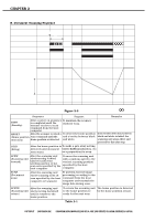
CHAPTER 2 D. Drive Motor Control Circuit Figure 2-14 shows a block diagram of the drive motor control circuit. The control program analyzes each command sent from the host computer and sends a command to generate motor clock to the gate array. The gate array generates the four phase motor drive pulse signals (MA+, MA-, MB+, MB-), which are sent to the drive motor via the motor driver. When the host computer changes the resolution, the control program sets to change the frequency of the motor drive pulse signals for the gate array, then changes the rotating speed of the drive motor. Host computer Control program Main PCB Gate array MA+ MBMB+ MA- Motor driver PA+ J2-1 PB- -2 PB+ -3 PA- -4 Drive motor M1 Figure 2-14 2 - 16 COPYRIGHT © 2000 CANON INC. CANOSCAN N650U/N656U/N1220U REV.0 JUNE 2000 PRINTED IN JAPAN (IMPRIME AU JAPON)
-
 1
1 -
2
-
3
-
4
-
5
-
6
-
7
-
8
-
9
-
10
-
11
-
12
-
13
-
14
-
15
-
16
-
17
-
18
-
19
-
20
-
21
-
22
-
23
-
24
-
25
-
26
-
27
-
 28
28 -
 29
29 -
 30
30 -
 31
31 -
 32
32 -
 33
33 -
 34
34 -
 35
35 -
 36
36 -
 37
37 -
 38
38 -
39
-
40
-
41
-
42
-
43
-
44
-
45
-
46
-
47
-
48
-
49
-
50
-
51
-
52
-
53
-
54
-
55
-
56
-
57
-
58
-
59
-
60
-
61
-
62
-
63
-
64
-
65
-
66
-
67
-
68
-
69
-
70
-
71
-
72
-
73
-
74
-
75
-
76
-
77
-
78
-
79
-
80
-
81
-
82
-
83
-
84
-
85
-
86
-
87
-
88
-
89
-
90
-
91
-
92
-
93
-
94
-
95
-
96
-
97
 |
 |
