Carvin C2040 Concert Series Operating Guide - Page 4
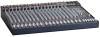
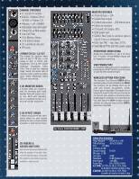
Channel Features, Master - 20 channel mixer
 |
View all Carvin C2040 manuals
Add to My Manuals
Save this manual to your list of manuals |
Page 4 highlights
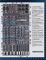
Quick Start Up Here are some brief instructions to get you going quickly. With the mixer unplugged and the unit turned off, complete the following procedures: 1. CONNECTING AC POWER TO YOUR MIXER • The mixer can be used with either 120 or 240VAC. • Use only a grounded (3 prong) power outlet to prevent a shock hazard and for the quietest grounding for your mixer. 2. CONNECTING INPUTS TO YOUR MIXER • For low level balanced devices such as microphones, plug into the balanced XLR MIC inputs. • For high level balanced or unbalanced devices such as instruments & keyboards, plug into the LINE input jacks using a shielded 1/4" cable. channel features 1. 1/4" Line INputs The line connectors are for connecting balanced and unbalanced instruments and line level sources such as drum machines, keyboards, ETC. 2. XLR MIC INputs The balanced Mic inputs are for connecting microphones with XLR connections. Both the Line and XLR MIC inputs can be used simultaneously. 3. Channel Insert/direct out To insert channel effects, compressor, etc. use a 1/4" TRS (Tip/Ring/Sleeve) cable. For a direct out from the channel, insert a standard 1/4" cable to the first "click" (half insert). 4. Gain The gain controls the input level for the channel. The green SIG LED indicates the incoming signal. The PEAK LED will flash red if the gain is set too high. Turn down the gain until the PEAK LED does not flash to avoid distortion. You can use the channel PFL switch to monitor the channel input level and use the meters to adjust the gain control to 0dB for optimal signal gain. 5. Low cut switch A 75 Hz low cut filter helps eliminate unwanted low frequencies. Great for reducing "boom" noise from mic stands or from acoustic/electric guitars. Turning up the LOW EQ when using this filter can help create a punchier bass response. 6. 3 band Active EQ The ±15 dB boost or cut gives an overall 30 dB range for powerful EQ control. The active circuits deliver deep bass from the 20-80 Hz LOW control. The MID control works from 100 to 5kHz, depending on the MID FREQ setting. The stereo channels feature a ±15 dB MID boost or cut. The HI control functions from 11-20k. Start out with all tone controls at their center "zero" position. Determine which position your MID FREQ sounds best, then cut or boost your HI and LOW frequencies as needed. Try various mics and mic placement on instruments before adjusting the EQ. A typical setting may be: HI -3, MID FREQ set at 700Hz -3 and LOW +3. 7. MID SWEEP These controls allow you to select which frequency that the MID control boost or cut. By adjusting the MID FREQ, you can select the exact frequency to boost or cut that will best complement various inputs. 700Hz is recommended for the MID FREQ control for guitar & vocals. Don't be afraid to adjust the HI, MID & LOW controls to get good presence and depth. This is one of the keys to great sound. 8. monitor 1 THRU 4 send controls The channel MONITORS allow you to create four independent monitor mixes. The MONITOR signals (pre-EQ, pre fader) are routed to the master MON 1, 2, 3, & 4 controls (#20) respectively before going to the XLR output connectors (#33). 3. TURNING YOUR MIXER ON • Adjust all channel FADERS and master level controls to their off positions • Adjust all channel's Hi, Mid, and Bass controls and the two master 9 Band GraphiCS to their center positions. • Adjust the Channel "PAN" controls to their center positions. • Turn the mixer on by the rear panel power switch and watch for the power LED. • Adjust the GAIN controls for the channels being used. Your mixer is now ready to operate. 9. Eff 1 & EFF 2 send CONTROLs The EFF 1 or eff 2 control sends signal (post EQ, post fader) from the channel to the master EFFECTS 1 or EFFECTS 2 levels to the internal processors (#19) and to the EFF 1 or eff 2 external output (#32). 10. PAN CONTROL Each channel's PAN control allows stereo imaging by panning Left or Right during recordings or live performances. The PAN control also works for the sub-mix groups. A center position will send a channel's signal to a pair of sub-group faders (1-2, 3-4 when assigned). By panning hard left, the signal is routed to only sub-group fader 1 or 3 when assigned. Panning hard right routes the signal to sub-mix fader 2 or 4. Dual element pan controls provide 15dB greater channel separation than standard pan controls 11. channel SIGNAL GREEN LED The signal LED is pre-fader and post EQ. This LED helps the operator verify that the channel is receiving a signal from the mic or instrument inputs even when the channel fader is off. 12. CHANNEL RED PEAK LED This peak indicator is pre-fader and post EQ. If the PEAK LED flashes, the channel needs a reduction with the GAIN control (#4) to prevent distortion. A "solid" lit PEAK LED indicates that the channel has been muted (#12). 13. CHANNEL MUTE SWITCH The MUTE switch will interrupt the channel signal. This feature saves having to reset your faders and monitor sends. The PEAK LED (#12) will light solid with no SIG LED. 14. CHANNEL PFL SWITCH This switch allows the operator to listen to a channel (pre fader listen) in the headphone mix to set EQ and gain levels as well as see the channel's level at the LED meter output (#28). 15. CHANNEL ASSIGNMENT SWITCHES These switches assign the channel's signal to the Master L/R faders or to the Sub-Group faders 1 & 2, 3 & 4 for sub-mixing in stereo pairs. For mono, pan fully to the left and assign a channel to Sub-Group fader 1 or 3 only. Pan fully to the right and assign a channel to Sub-Group fader 2 or 4. Likewise assigning the L/R switches sends the channel directly to the main L or R faders. 16. CHANNEL FADER The CHANNEL FADER adjusts the output level of the channel. The signal will go to one or more of the Master Faders, depending on both the Channel Assignment switches and the PAN control. Calibrated 60mm faders with audio tapers are featured for smooth fade-outs. Slide all faders down when connecting your inputs. The featured dust covers will hold the faders in place if not used over a period of time. 17. PHANTOM POWER SWITCH/RED LED This switch provides +48v power for condenser mics such as Carvin's M90S in groups of 8 channels. This leaves the remaining MIC inputs for sources that don't require phantom power. The LINE inputs are unaffected. 18. STEREO CHANNELS The last 2 channels are for line level stereo sources such as keyboards, CD/MP3 ETC. Connect either 1/4" audio cables or RCA cables. These stereo channels can also be used as stereo returns if using outboard stereo effects processors. MASTER SECTION 19. DUAL STEREO 24-BIT EFFECTS The internal 24-BIT stereo processors receive signals from the channel EFF1 and EFF2 controls and the master EFF1 and EFF2 controls. If the adjacent PK (peak) LED flashes, reduce the level from the channel or master EFF1 or EFF2 send controls. A "solid" PK LED will show EFFECTS 1 or 2 have been muted by the MUTE switches. The RETURN control will adjust the volume level of the selected effects. Remember each channel has its own two EFFECT sends that will send the signal to the effects processors. The red PK LED will indicate when the effects signal from the channel is distorting. Reduce the level of the channel EFFECT control until the PK LED stops flashing. EFFECT AND PARAMETERS a.) ECHO: When the SELECT control is at the "seven O'clock" position, it is selected to the first ECHO setting where you get a single repeat echo (minimal regeneration). Turning the PARAMETER to 1 will provide the shortest delay time between the original signal and the echo. Increasing the PARAMETER to the right will increase the time delay between the original signal and the echo. To increase the number of echo repeats, turn the SELECT up. b.) REVERB: When the SELECT is at the "ten O'clock" position, it is selected to the first REVERB setting. Turning the SELECT clockwise will increase the amount of high frequencies in the reverb. Turning the PARAMETER to 1 will provide minimal decay time of the reverb. Increasing to the right will increase the reverb decay time. c.) CHORUS: When the SELECT is at the "one O'clock" position it is selected to the first CHORUS setting. Turning the SELECT clockwise will increase the amount reverb in the chorus. Turning the PARAMETER to 1 will provide a minimal chorus depth setting. Increasing to the right will increase the chorus depth. d.) FLANGE: When the SELECT is at the "four O'clock" position it is selected to the first FLANGE setting. Turning the SELECT clockwise will increase the flanger's speed. Turning the PARAMETER to 1 will provide minimal flanging depth. Increasing to the right will increase the flanger's depth. To send effects to the monitors, use the MONITORS controls in the effects section. Turning the control left sends effects to MON 1.Turning to the right sends effects to MON 2. The center position on both controls is OFF. (#19) 20. MASTER MONITOR 1-4 CONTROLS These are the master outputs for the 4 monitor sends. These correspond to the Mon 1-4 XLR output jacks (#33). 21. MASTER EFF 1 & 2 SEND Sends signals from each channel EFF 1 & EFF2 sends to the internal processors and to the EFF1 & EFF2 outputs (#32). 22. GROUP/SUB-MIX FADERS 1-4 Once a channel has been assigned to one of these faders, the four faders can be used to either submix the L/R main mix or control the SUB GROUP (#34) output level. 23. GROUP ASSIGNMENT SWITCHES These switches assign/send the sub-group mix to the main L/R faders. For mono mixing, assign to both L/R. To bus out to the 4 XLR outputs, do not assign to L/R. 24. MASTER L/R FADERS These faders adjust the level of the main stereo output created by all channels and groups assigned to L/R faders. Output appears at the L/R balanced XLR connectors (#36).
-
 1
1 -
 2
2 -
 3
3 -
 4
4 -
 5
5 -
 6
6 -
 7
7 -
 8
8
 |
 |
