Carvin C3248 Concert Series Operating GUide - Page 11
Left & Right Xlr Output Connectors
 |
View all Carvin C3248 manuals
Add to My Manuals
Save this manual to your list of manuals |
Page 11 highlights
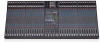
17 40 41 38 39 46 1 44 2 3 45 42 43 4 36 5 6 35 7 34 37 6 8 33 19 20 21 18 32 19, 20, 21 31 9 30 22 10 29 11 27 12 26 13 14 24 15 16 23 25 28 25. GROUP ASSIGNMENT SWITCHES These switches send the sub-group mix to the main L/R faders. For mono mixing, assign to both L/R. 26. 1-4 GROUP COMPRESSORS/LEDs Each of the 4 sub groups features a compressor, which will reduce the output when it gets above the level you set with the COMP control. Set at "0" there is no effect. As you turn UP the COMP knob, the lower the maximum level. The compressor circuit is pre-fader, so you can set the COMP once and still adjust the group fader as needed. The LED will indicate when the compressor is working. 27. COMP LINK SWITCHES These switches link the COMP controls for stereo pairs of equal setting. The COMP1 or COMP3 control becomes the master for the pair. Link 1-2 or 3-4. 28. MASTER L/R FADERS These faders adjust the level of the main stereo output created by all channels and groups assigned to L/R faders. Output appears at the L/R balanced XLR connectors (#44). 29. MONO/SUB CONTROL A mono output is created from the L/R master faders (post) for center, subwoofers, or side fill speakers. The output is at the MONO/SUB XLR connector (#45). 30. REC OUT/USB CONTROL This control sets the level sent to REC OUT L-R RCA jacks and to the rear USB port. The signal source is the main L-R mix (pre-fader). 31. HEADPHONE AND METER SOURCE The stereo PHONES control sets the level of the PHONES jack (#42). The PFL, L/R, MONO, MON 1-MON 6, USB IN, and REC OUT USB switches allow for monitoring of these sources through the headphones and the L/R LED METERS (#33). 32. PFL RED LED Indicates that the headphone & meters are monitoring only the channels or groups where the PFL is switched on. 33. L/R LED VU METERS This group of 10 LED's offer 6 dB increment resolution that give the operator a visual indication of the mixer's output levels, selectable by the METER SOURCE or PFL switches (#31). 34. DUAL 9 BAND GRAPHIC EQs are one octave filters at 63,125, 250, 500, 1k, 2k, 4k, 8k & 16k Hz centers that offer ±12dB adjustment to help eliminate feedback & enhance tone for the main or monitor mix. 35. EQ SWITCH 1 & 2 These switches swap the 9 band EQ's from the standard L/R main outputs "OUT" to the MON 1 & MON 2 outputs "IN" respectively. 36. USB POWER PORTS Use these ports to supply +5V USB power to run accessories like LED lighting or to charge MP3 players. Connect audio outputs to RETURNS 3 or 4, or to channel inputs. 37. POWER BLUE LED Verifies the mixer is on. 38. EFFECTS 1 & 2 OUTPUT JACKS 1/4" outputs drive external effects. Connect your effects processor's inputs to these jacks. 39. RETURNS 3 & 4 L-R INPUT JACKS Returns a stereo signal from an external effect. Connect your effects processors' stereo outputs to these jacks. If only one jack is used, the mono signal will go to both L/R . 40. MONITOR 1-6 XLR OUTPUTS The C SERIES provides balanced XLR outputs. Connect your monitor power amps to these connectors. 41. GROUP 1-4 OUTPUT JACKS The C SERIES provides 4 balanced 1/4" outputs. Connect your 4-track recorder or side fill power amps to these jacks. 42. HEADPHONE JACK 1/4" stereo jack for headphone or control room output. 43. REC OUT L-R RCA JACKS RCA jacks for connecting to a recorder input. 44. LEFT & RIGHT XLR OUTPUT CONNECTORS This set of balanced XLR connectors are for connecting the main L/R output to power amps or recording gear. 45. MONO/SUB XLR OUTPUT CONNECTOR A bal. XLR output is featured for side fills or subwoofers. 46. REAR USB CONNECTOR This rear USB connector will transmit audio to and from a computer for recording with compatible software and drivers. Output signal is the pre-fader L-R stereo mix sent via the REC OUT USB LEVEL. Input from a computer comes into the RETURN 4 bus, controlled at the RTN4/ USB control. 11
-
 1
1 -
2
-
3
-
4
-
5
-
 6
6 -
 7
7 -
 8
8 -
 9
9 -
 10
10 -
 11
11 -
 12
12 -
 13
13 -
 14
14 -
 15
15 -
 16
16
 |
 |
