Carvin C3248 Concert Series Operating GUide - Page 8
Powered C1648P
 |
View all Carvin C3248 manuals
Add to My Manuals
Save this manual to your list of manuals |
Page 8 highlights
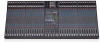
Powered C1648P C1648P Rear 1 C1648P Power Specs 4x 500w @ 4 ohms (2000w) 4x 300w @ 8 ohms (1200w) 6 4 52 Removable plate for 3 optional wireless systems Handle C1648P REAR PANEL OPERATION: 1. SPEAKER OUTPUTS The combination SPEAKON jacks also accept 1/4" plugs. 12 Gauge SPEAKON speaker cables are an industry standard for high power applications (pin 1+ is POS, pin 1- is NEG, pins 2+ and 2- are not used). Use only 16 gauge (or heavier) 1/4" speaker cables, NOT shielded instrument cables. Turn power off before connecting speaker cables. The minimum load for each amp is 4 OHMS. Chaining together more than one speaker on an output is fine as long as the total impedance is not below 4 ohms. If the speaker load is lower than 4 ohms, the amp may go into one of the PROTECT modes. (Two 8 ohm speakers in parallel = 4 ohms). FREE Carvin Impedance Calculator iPhone App at Carvin.com/iphone. 2. AMP ROUTING switch will select between two internally routed configurations. OUT: AMP1-LEFT, AMP2-RIGHT, AMP3-MONITOR1, AMP4MONITOR2. IN: 1 amp each, for Monitors 1 thru 4. Speaker output levels are adjusted from the Left/Right faders or Monitor 1-4 controls. The front panel GRAPHIC EQs function with the amps, depending on the front panel EQ1 and EQ2 switch settings. 3. AMP PATCH INSERT jacks offer flexibility for mixer to amp signal routing. These jacks are T-R-S (Tip-Ring-Sleeve). TIP is the power amp input. RING is the signal sent from the mixer determined by the AMP ROUTING switch. The limiters are post insert. Patching a compressor or equalizer between the mixer and the amp can be done by using a stereo insert cable (like Carvin's AP1). Connect the RING signal to the INPUT of the external device, and the TIP signal from the OUTPUT of the device. Plugging in a standard 1/4" cable (mono) into the AMP PATCH INSERT jacks allows any external signal to be sent to the internal power amps. For example, you may want to patch the GROUP outputs (1-4) into the power amps. Plug one end of each cable into the GROUP jacks on the top panel of the mixer. -Plug the other ends of the cables into the AMP PATCH INSERT jacks. The GROUP 1-4 faders will now control what is heard at the SPEAKER OUTPUTS. 4. AMP CLIP LEDs - The red CLIP LEDs will flash when an amp has reached it's maximum output. Occasional flashing caused by bass frequencies is OK. Consistent flashing caused by higher frequencies may damage drivers due to excessive distortion. This will not damage the amp. 5. PROTECT LED - The yellow LED indicates the power amp system has gone into one of its protection modes. There will be no output from the amps. If the amp output has been short circuited, or overloaded by putting less than 4 ohms on the output the amp will go into protection. Check for shorted speaker cables and speaker impedance, then reset the POWER switch (off-on). If the amp has overheated, lower the volume and make sure the fan vents are not blocked. Wait for the fan to cool the amps. Normal operation will return in about 1-3 minutes. 88
-
 1
1 -
2
-
 3
3 -
 4
4 -
 5
5 -
 6
6 -
 7
7 -
 8
8 -
 9
9 -
 10
10 -
 11
11 -
 12
12 -
 13
13 -
14
-
15
-
16
 |
 |
