Celestron SkyProdigy 130 Computerized Telescope SkyProdigy Series Manual (Engl - Page 8
ASSEMBLY, Assembling SkyProdigy, Attaching the Hand Control Holder, Attaching the Fork Arm to
 |
View all Celestron SkyProdigy 130 Computerized Telescope manuals
Add to My Manuals
Save this manual to your list of manuals |
Page 8 highlights
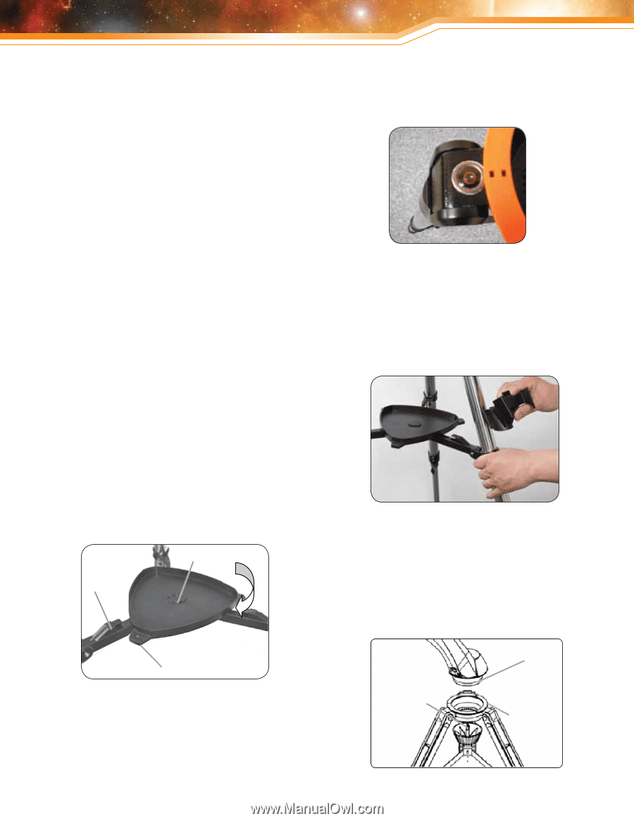
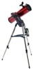
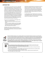
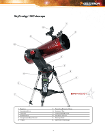
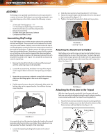
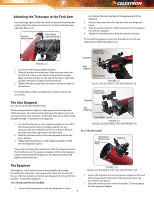
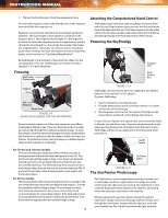
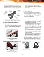
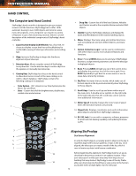
INSTRUCTION MANUAL [Continued] ASSEMBLY SkyProdigy comes partially assembled and can be operational in a matter of minutes. SkyProdigy is conveniently packaged in one reusable shipping carton that contains the following accessories: • 25 mm and 9 mm Eyepieces - 1¼" • 1¼" Star Diagonal (SkyProdigy 70 and 90 only) • StarPointer Finderscope and Mounting Bracket • Deluxe Accessory Tray • TheSkyX First Light Astronomy Software • Computerized Hand Control Assembling SkyProdigy Your SkyProdigy comes in three major sections: the optical tube, fork arm and tripod. These sections can be attached in seconds using the quick release coupling screw located under the tripod mounting platform and the dovetail mounting clamp located on the inside of the fork arm. To begin, remove all of the accessories from their individual boxes. Remember to save all of the containers so that they can be used to transport the telescope. Before attaching the visual accessories, the telescope tube and fork arm should be mounted to the tripod. First, install the accessory tray onto the tripod legs: 1. Remove the tripod from the box and spread the legs apart until the center leg brace is fully extended. 2. Locate the accessory tray, and place it on top of the tripod center support brace in between the tripod legs (see figure 2-1). 3. Rotate the accessory tray so that the central hole in the tray slides over the flange post in the center of the support bracket. 4. Finally, rotate the tray so that the locking tabs slide under the locking clips on the support bracket. You will hear the tray snap into place. Locking Clips Flange Post 2. Slide the inner portion of each leg down 6" to 8" inches. 3. Adjust the tripod height until the bubble level on the tripod leg is centered (See figure 2-2). 4. Tighten the tripod locking bolts to hold each leg in place. Figure 2-2 Leveling Tripod Attaching the Hand Control Holder SkyProdigy comes with a snap-on hand control holder that conveniently attaches to any of the tripod legs. To attach the hand control holder simply position the holder with the square plastic tab facing up and push against the tripod leg until it snaps into place (See figure 2-3). Figure 2-3 Attaching the Fork Arm to the Tripod With the tripod properly assembled, the telescope tube and fork arm can easily be attached using the quick release coupling screw located underneath the tripod mounting platform: 1. Place the fork arm base inside the tripod mounting platform. 2. Thread the coupling screw into the hole at the bottom of the fork arm base and hand tighten (See figure 2-4). Locking Tabs Figure 2-1 It is a good idea to level the tripod and adjust the height of the tripod legs before attaching the fork arm and tube. Minor adjustments can be made later. To adjust the height of the tripod legs: 1. Loosen the tripod leg locking bolt located on the side of each leg. 8 Fork Arm Base Coupling Screw Tripod Mounting Platform Figure 2-4
-
 1
1 -
2
-
 3
3 -
 4
4 -
 5
5 -
 6
6 -
 7
7 -
 8
8 -
 9
9 -
 10
10 -
 11
11 -
 12
12 -
 13
13 -
14
-
15
-
16
-
17
-
18
-
19
-
20
-
21
-
22
-
23
-
24
-
25
-
26
-
27
-
28
-
29
-
30
-
31
-
32
 |
 |