Chamberlain B550 B550 B552 B750 Owner s Manual - English - Page 9
STEP 4 Install the belt,
 |
View all Chamberlain B550 manuals
Add to My Manuals
Save this manual to your list of manuals |
Page 9 highlights
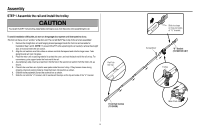
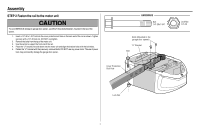
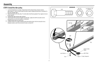
Assembly STEP 4 Install the belt 1. Pull the belt around the idler pulley and toward the trolley. The ribbed side must contact the pulley. 2. Hook the trolley connector into the retaining slot on the trolley as shown (Figure 1). 3. With the trolley against the screwdriver, dispense the remainder of the belt along the rail length toward the motor unit and around the sprocket (Figure 2). The sprocket teeth must engage the belt. 4. Check to make sure the belt is not twisted. Connect the trolley threaded shaft with the master link (Figure 3). l Push pins of master link bar through holes in end of belt and trolley threaded shaft. l Push master link cap over pins and past pin notches. l Slide the closed end of the clip-on spring over one of the pins. Push the open end of the clip-on spring onto the other pin. 5. Remove the spring trolley nut from the threaded shaft. 6. Insert the trolley threaded shaft through the hole in the trolley. HARDWARE Threaded Shaft with Spring Trolley Nut Master Link Figure 1 Trolley Connector Retaining Slot Figure 2 Sprocket Master Link Threaded Shaft Figure 3 9
-
 1
1 -
2
-
3
-
 4
4 -
 5
5 -
 6
6 -
 7
7 -
 8
8 -
 9
9 -
 10
10 -
 11
11 -
 12
12 -
 13
13 -
 14
14 -
15
-
16
-
17
-
18
-
19
-
20
-
21
-
22
-
23
-
24
-
25
-
26
-
27
-
28
-
29
-
30
-
31
-
32
-
33
-
34
-
35
-
36
-
37
-
38
-
39
-
40
-
41
-
42
-
43
-
44
-
45
-
46
-
47
-
48
 |
 |
