Cisco 1232AG Hardware Installation Guide - Page 74
Step 5, Caution, Location of Product Compliance Labels
 |
UPC - 882658058363
View all Cisco 1232AG manuals
Add to My Manuals
Save this manual to your list of manuals |
Page 74 highlights
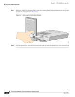
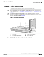
Installing a 2.4-GHz Radio Chapter 7 2.4-GHz Radio Upgrade Step 5 Insert the radio card into the access point's mini-PCI connector by following these steps: a. Tilt the radio card at approximately 20o to 30o so that its gold pins are aligned with the mini-PCI connector (see Figure 7-4). Step 6 Step 7 b. Push the card into the mini-PCI connector until it clicks into place. Carefully push the card down (towards the access point's motherboard) until the card-retaining clips lock into the notches on the side of the radio card (you will hear a click). Carefully position the antenna wires so that the metal connectors do not touch each other. Caution Damage to the radio could occur if the antenna connectors are touching when power is applied. If they are touching, carefully rotate them in opposite directions until they are separated. Step 8 Step 9 Step 10 Reinstall the 2.4-GHz radio access cover and use the T-10 tamper-resistant Torx L-wrench to tighten the cover's retaining screw. Remove the backing paper from the 2.4-GHz radio product compliance label. Carefully attach the label in the space provided below the access point's product compliance label as shown in Figure 7-5. Figure 7-5 Location of Product Compliance Labels 1 2 74246 1 2.4-GHz radio product compliance label 2 Access point product compliance label Note If your access point contains a 5-GHz radio module, there is also a 5-GHz radio product compliance label on the back of the unit. The radio card installation is now complete. To configure the radio with your wireless network settings, refer to the Cisco IOS Software Configuration Guide for Cisco Aironet Access Points. Cisco Aironet 1200 Series Access Point Hardware Installation Guide 7-8 OL-4310-01
-
 1
1 -
2
-
3
-
4
-
5
-
6
-
7
-
8
-
9
-
10
-
11
-
12
-
13
-
14
-
15
-
16
-
17
-
18
-
19
-
20
-
21
-
22
-
23
-
24
-
25
-
26
-
27
-
28
-
29
-
30
-
31
-
32
-
33
-
34
-
35
-
36
-
37
-
38
-
39
-
40
-
41
-
42
-
43
-
44
-
45
-
46
-
47
-
48
-
49
-
50
-
51
-
52
-
53
-
54
-
55
-
56
-
57
-
58
-
59
-
60
-
61
-
62
-
63
-
64
-
65
-
66
-
67
-
68
-
 69
69 -
 70
70 -
 71
71 -
 72
72 -
 73
73 -
 74
74 -
 75
75 -
 76
76 -
 77
77 -
 78
78 -
 79
79 -
80
-
81
-
82
-
83
-
84
-
85
-
86
-
87
-
88
-
89
-
90
-
91
-
92
-
93
-
94
-
95
-
96
-
97
-
98
-
99
-
100
-
101
-
102
-
103
-
104
-
105
-
106
-
107
-
108
-
109
-
110
-
111
-
112
-
113
-
114
-
115
-
116
-
117
-
118
-
119
-
120
-
121
-
122
-
123
-
124
-
125
-
126
-
127
-
128
 |
 |
