Cisco 3550-12T Hardware Installation Guide - Page 22
Front-Panel Description - 24pwr
 |
UPC - 746320521411
View all Cisco 3550-12T manuals
Add to My Manuals
Save this manual to your list of manuals |
Page 22 highlights
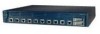
Front-Panel Description Chapter 1 Product Overview Table 1-1 Switch Features (continued) Feature Inline Power2 Description • Power for Cisco IP Phones and access points from all 10/100 Ethernet ports • Auto-detection and control of inline power on a per-port basis on all 10/100 ports • Support for fan-fault and overtemperature detection through the Network Assistant and the device manager. 1. Gigabit Interface Converter 2. Only Catalyst 3550-24PWR switch Front-Panel Description The switch front panel includes the 10/100 or 10/100/1000 Ethernet ports or 100BASE-FX ports, GBIC module slots, and switch LEDs as shown in Figure 1-3 and described on the following pages. Note Figure 1-3 shows the Catalyst 3550-12T switch as an example. All the Catalyst switches have similar components. Figure 1-3 Switch Front Panel 3 SYSTEM RPS STATUS UTIL DUPLX SPEED MODE 1 2 3 4 5 6 7 8 9 10 Catalyst 3550 SERIES 1 2 101603 12 4 5 1 Mode button 2 Switch LEDs 3 Port LEDs 4 10/100 or 10/100/1000 Ethernet ports or 100BASE-FX ports1 5 GBIC slots 1. Port numbering is from left to right, with port 1 on the far left. For ports grouped in pairs, the first member of the pair (port 1) is above the second member (port 2). The GBIC slots are numbered 1 (left) and 2 (right) or 1 (above) and 2 (below). Catalyst 3550 Switch Hardware Installation Guide 1-4 OL-6155-01
-
 1
1 -
2
-
3
-
4
-
5
-
6
-
7
-
8
-
9
-
10
-
11
-
12
-
13
-
14
-
15
-
16
-
 17
17 -
 18
18 -
 19
19 -
 20
20 -
 21
21 -
 22
22 -
 23
23 -
 24
24 -
 25
25 -
 26
26 -
 27
27 -
28
-
29
-
30
-
31
-
32
-
33
-
34
-
35
-
36
-
37
-
38
-
39
-
40
-
41
-
42
-
43
-
44
-
45
-
46
-
47
-
48
-
49
-
50
-
51
-
52
-
53
-
54
-
55
-
56
-
57
-
58
-
59
-
60
-
61
-
62
-
63
-
64
-
65
-
66
-
67
-
68
-
69
-
70
-
71
-
72
-
73
-
74
-
75
-
76
-
77
-
78
-
79
-
80
-
81
-
82
-
83
-
84
-
85
-
86
 |
 |
