Cisco 3845 Hardware Installation Guide - Page 369
Step 1, Slide the network module out of the slot.
 |
UPC - 746320981420
View all Cisco 3845 manuals
Add to My Manuals
Save this manual to your list of manuals |
Page 369 highlights
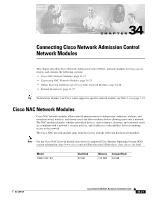
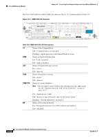
Chapter 34 Connecting Cisco Network Admission Control Network Modules Online Insertion and Removal of Cisco NAC Network Modules To perform online removal of a network module and insertion of a replacement, follow these steps, beginning in privileged EXEC mode: Step 1 Initiate a network module session using the following command: Router# service-module integrated-service-engine 1/0 session Trying 10.10.10.1, 2065 ... Open Press RETURN to get started! Router> enable Router# Step 2 Save the running configuration of the network module by using the following command from the router # prompt: Router# copy running-config tftp tftp-server-address filename Step 3 Step 4 Exit the network module session by pressing Control-Shift-6, followed by x. On the router, clear the integrated-service-engine console session by using the following command: Router# service-module integrated-service-engine slot/unit session clear Step 5 Perform a graceful shutdown of the network module disk drive by using the following command: Router# service-module integrated-service-engine slot/unit shutdown Step 6 Shut down the network module interface: Router (config)# interface integrated-service-engine slot/unit Router (config-if)# shutdown Router (config-if)# exit Step 7 Step 8 Step 9 Step 10 Unplug all network interface cables from the network module. Loosen the two captive screws holding the network module in the chassis slot. Slide the network module out of the slot. Align the replacement network module with the guides in the chassis slot, and slide it gently into the slot. Note If the router is not fully configured with network modules, make sure that blank panels fill the unoccupied chassis slots to provide proper airflow. Step 11 Step 12 Step 13 Push the module into place until you feel its edge connector mate securely with the connector on the backplane. Reconnect the network interface cables that you disconnected in Step 7. Check that the network module LEDs are on and that the power (PWR) and enable (EN) LEDs on the front panel are also on. This inspection ensures that connections are secure and that the new unit is operational. OL-2485-20 Cisco Network Modules Hardware Installation Guide 34-25
-
 1
1 -
2
-
3
-
4
-
5
-
6
-
7
-
8
-
9
-
10
-
11
-
12
-
13
-
14
-
15
-
16
-
17
-
18
-
19
-
20
-
21
-
22
-
23
-
24
-
25
-
26
-
27
-
28
-
29
-
30
-
31
-
32
-
33
-
34
-
35
-
36
-
37
-
38
-
39
-
40
-
41
-
42
-
43
-
44
-
45
-
46
-
47
-
48
-
49
-
50
-
51
-
52
-
53
-
54
-
55
-
56
-
57
-
58
-
59
-
60
-
61
-
62
-
63
-
64
-
65
-
66
-
67
-
68
-
69
-
70
-
71
-
72
-
73
-
74
-
75
-
76
-
77
-
78
-
79
-
80
-
81
-
82
-
83
-
84
-
85
-
86
-
87
-
88
-
89
-
90
-
91
-
92
-
93
-
94
-
95
-
96
-
97
-
98
-
99
-
100
-
101
-
102
-
103
-
104
-
105
-
106
-
107
-
108
-
109
-
110
-
111
-
112
-
113
-
114
-
115
-
116
-
117
-
118
-
119
-
120
-
121
-
122
-
123
-
124
-
125
-
126
-
127
-
128
-
129
-
130
-
131
-
132
-
133
-
134
-
135
-
136
-
137
-
138
-
139
-
140
-
141
-
142
-
143
-
144
-
145
-
146
-
147
-
148
-
149
-
150
-
151
-
152
-
153
-
154
-
155
-
156
-
157
-
158
-
159
-
160
-
161
-
162
-
163
-
164
-
165
-
166
-
167
-
168
-
169
-
170
-
171
-
172
-
173
-
174
-
175
-
176
-
177
-
178
-
179
-
180
-
181
-
182
-
183
-
184
-
185
-
186
-
187
-
188
-
189
-
190
-
191
-
192
-
193
-
194
-
195
-
196
-
197
-
198
-
199
-
200
-
201
-
202
-
203
-
204
-
205
-
206
-
207
-
208
-
209
-
210
-
211
-
212
-
213
-
214
-
215
-
216
-
217
-
218
-
219
-
220
-
221
-
222
-
223
-
224
-
225
-
226
-
227
-
228
-
229
-
230
-
231
-
232
-
233
-
234
-
235
-
236
-
237
-
238
-
239
-
240
-
241
-
242
-
243
-
244
-
245
-
246
-
247
-
248
-
249
-
250
-
251
-
252
-
253
-
254
-
255
-
256
-
257
-
258
-
259
-
260
-
261
-
262
-
263
-
264
-
265
-
266
-
267
-
268
-
269
-
270
-
271
-
272
-
273
-
274
-
275
-
276
-
277
-
278
-
279
-
280
-
281
-
282
-
283
-
284
-
285
-
286
-
287
-
288
-
289
-
290
-
291
-
292
-
293
-
294
-
295
-
296
-
297
-
298
-
299
-
300
-
301
-
302
-
303
-
304
-
305
-
306
-
307
-
308
-
309
-
310
-
311
-
312
-
313
-
314
-
315
-
316
-
317
-
318
-
319
-
320
-
321
-
322
-
323
-
324
-
325
-
326
-
327
-
328
-
329
-
330
-
331
-
332
-
333
-
334
-
335
-
336
-
337
-
338
-
339
-
340
-
341
-
342
-
343
-
344
-
345
-
346
-
347
-
348
-
349
-
350
-
351
-
352
-
353
-
354
-
355
-
356
-
357
-
358
-
359
-
360
-
361
-
362
-
363
-
 364
364 -
 365
365 -
 366
366 -
 367
367 -
 368
368 -
 369
369 -
 370
370 -
 371
371 -
 372
372 -
 373
373 -
 374
374 -
375
-
376
-
377
-
378
-
379
-
380
-
381
-
382
-
383
-
384
-
385
-
386
-
387
-
388
-
389
-
390
-
391
-
392
-
393
-
394
-
395
-
396
-
397
-
398
-
399
-
400
-
401
-
402
-
403
-
404
-
405
-
406
-
407
-
408
-
409
-
410
-
411
-
412
-
413
-
414
-
415
-
416
-
417
-
418
 |
 |