Cisco 7204 Installation Guide - Page 19
Port Adapter Slot Numbering, Cisco 7204 Router-Rear View - power supply
 |
UPC - 746320286631
View all Cisco 7204 manuals
Add to My Manuals
Save this manual to your list of manuals |
Page 19 highlights
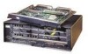
Chapter 1 Product Overview Physical Description Note In Figure 1-1 and Figure 1-2, a blank port adapter is installed in slot 3. To ensure adequate airflow across the port adapters, each port adapter slot must be filled with either a port adapter or a blank port adapter. Figure 1-2 Port Adapter Slot Numbering Blank port adapter Port adapter slot 4 Port adapter slot 2 Port adapter slot 3 Port adapter slot 1 EN TD TC RD RC LB CD TD TC RD RC LB CD TD TC RD RC LB CD ENABLED 0 3 1 ENABLED PCMCIA 1 2 3 0 1 LINK 2 3 ENABLED ETHERNET 10BT FAST SERIAL EN RX 0 TX TD TC RD RC LB CD SLOT 1 EJECT SLOT 0 MII FE II MEN RJE4N5 RJL4IN5K R 1O POWK RJ-45 CPU RESET RX 1 TX RX 0 2 TX RX 3 TX MII LINK RJ45 Cisco 7200 SERIES FAST ETHERNET 4 ETHERNET-10BFL 2 FAST ETHERNET INPUT/OUTPUT CONTROLLER 0 RX 4 TX Port adapter slot 0 H7399 The rear of the Cisco 7204 router provides access to the network processing engine and up to two power supplies (refer to Figure 1-3). Figure 1-3 Cisco 7204 Router-Rear View Chassis grounding receptacles Power supply filler plate AC-input receptacle Internal fans H6423 NETWORK PROCESSING ENGINE-150 Network processing engine AC-input or network services engine power supply Power switch Note The network processing engine does not support OIR. You must power down the Cisco 7204 before removing the network processing engine from the router. The network processing engine has no external connectors or LEDs. There is a handle for removing and installing the network processing engine and two captive installation screws for securing it to the chassis. OL-5101-02 Cisco 7204 Installation and Configuration Guide 1-3
-
 1
1 -
2
-
3
-
4
-
5
-
6
-
7
-
8
-
9
-
10
-
11
-
12
-
13
-
 14
14 -
 15
15 -
 16
16 -
 17
17 -
 18
18 -
 19
19 -
 20
20 -
 21
21 -
 22
22 -
 23
23 -
 24
24 -
25
-
26
-
27
-
28
-
29
-
30
-
31
-
32
-
33
-
34
-
35
-
36
-
37
-
38
-
39
-
40
-
41
-
42
-
43
-
44
-
45
-
46
-
47
-
48
-
49
-
50
-
51
-
52
-
53
-
54
-
55
-
56
-
57
-
58
-
59
-
60
-
61
-
62
-
63
-
64
-
65
-
66
-
67
-
68
-
69
-
70
-
71
-
72
-
73
-
74
-
75
-
76
-
77
-
78
-
79
-
80
-
81
-
82
-
83
-
84
-
85
-
86
-
87
-
88
-
89
-
90
-
91
-
92
-
93
-
94
-
95
-
96
-
97
-
98
-
99
-
100
-
101
-
102
-
103
-
104
-
105
-
106
-
107
-
108
-
109
-
110
-
111
-
112
-
113
-
114
-
115
-
116
-
117
-
118
-
119
-
120
-
121
-
122
-
123
-
124
-
125
-
126
-
127
-
128
-
129
-
130
-
131
-
132
-
133
-
134
-
135
-
136
-
137
-
138
-
139
-
140
-
141
-
142
 |
 |
