Cisco 7204 Installation Guide - Page 73
Providing a Chassis Ground Connection for the Router Chassis
 |
UPC - 746320286631
View all Cisco 7204 manuals
Add to My Manuals
Save this manual to your list of manuals |
Page 73 highlights
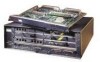
Chapter 3 Installing the Cisco 7204 Providing a Chassis Ground Connection for the Router Chassis To secure port adapter interface cables to the cable-management brackets, complete the following steps: Note The eight removable tie wraps installed on the cable-management brackets secure port adapter interface cables to the brackets. We recommend that you use the tie wraps that shipped with the cable-management brackets. You can use standard tie wraps; however, you will have to cut and replace them with new tie wraps when you want to release or secure an interface cable to a bracket. Step 1 Step 2 Select a tie wrap and release its locking mechanism. Carefully lace the interface cables from a port adapter installed in the chassis between the two ends of the unlocked tie wrap. Note Be sure to leave a small service loop in the interface cable before securing it to the cable-management bracket. Step 3 With the interface cables between the ends of the tie wrap and the interface cables' service loop in place, tighten the cable tie down around the interface cables until they are secured against the cable-management bracket. (Refer to Figure 3-10.) Figure 3-10 Securing Interface Cables to the Cable-Management Brackets ENABLED 0 MII LINK RJ45 3 1 ENABLED PCMCIA FAST ETHERNET SLOT 1 EJECT SLOT 0 MII FE II MEN RJE4N5 RJL4IN5K R 1O POWK RJ-45 CPU RESET EN RX 0 TX RX 1 TX RX 2 TX RX 3 TX RX 4 TX EN 0 1 2 3 4 5 6 7 SERIAL-EIA/TIA-232 4 ETHERNET-10BFL 2 FAST ETHERNET INPUT/OUTPUT CONTROLLER 0 H9237 Step 4 Service loop Repeat Step 1 through Step 3 for any other port adapter interface cables installed in the router. This completes the procedure for securing port adapter interface cables to the cable-management brackets. Proceed to the following section, "Providing a Chassis Ground Connection for the Router Chassis," to continue the installation. Providing a Chassis Ground Connection for the Router Chassis Before you connect power or turn on power to your router, we strongly recommend that you provide an adequate chassis ground (earth) connection for your router's chassis. Chassis grounding receptacles are provided on each Cisco 7204 router chassis. (Refer to Figure 1-3.) OL-5101-02 Cisco 7204 Installation and Configuration Guide 3-11
-
 1
1 -
2
-
3
-
4
-
5
-
6
-
7
-
8
-
9
-
10
-
11
-
12
-
13
-
14
-
15
-
16
-
17
-
18
-
19
-
20
-
21
-
22
-
23
-
24
-
25
-
26
-
27
-
28
-
29
-
30
-
31
-
32
-
33
-
34
-
35
-
36
-
37
-
38
-
39
-
40
-
41
-
42
-
43
-
44
-
45
-
46
-
47
-
48
-
49
-
50
-
51
-
52
-
53
-
54
-
55
-
56
-
57
-
58
-
59
-
60
-
61
-
62
-
63
-
64
-
65
-
66
-
67
-
 68
68 -
 69
69 -
 70
70 -
 71
71 -
 72
72 -
 73
73 -
 74
74 -
 75
75 -
 76
76 -
 77
77 -
 78
78 -
79
-
80
-
81
-
82
-
83
-
84
-
85
-
86
-
87
-
88
-
89
-
90
-
91
-
92
-
93
-
94
-
95
-
96
-
97
-
98
-
99
-
100
-
101
-
102
-
103
-
104
-
105
-
106
-
107
-
108
-
109
-
110
-
111
-
112
-
113
-
114
-
115
-
116
-
117
-
118
-
119
-
120
-
121
-
122
-
123
-
124
-
125
-
126
-
127
-
128
-
129
-
130
-
131
-
132
-
133
-
134
-
135
-
136
-
137
-
138
-
139
-
140
-
141
-
142
 |
 |
