Cisco ASR1002 Quick Start Guide - Page 14
Start the System, Connect Power to the Cisco ASR 1002 Router - pwr ac
 |
UPC - 882658196416
View all Cisco ASR1002 manuals
Add to My Manuals
Save this manual to your list of manuals |
Page 14 highlights
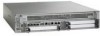
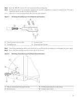
Figure 11 Cisco ASR 1002 Integrated Route Processor Cable-Managements 1234 5 STATUS A/L C/A A/L C/A A/L C/A STATUS ASR 1002 stat min pwr maj crit STAT QE0 QE1 QE2 QE3 BOOT CARRIER MTS LINK MGMT AUX CON PWR STAT SPA-4XOC3-POS 0 0 A/L C/A A/L C/A 1 1 A/L C/A 2 2 A/L C/A 3 3 A/L C/A SPA-4XOC3-POS SPA-4XOC3-POS 0 A/L C/A 1 A/L C/A 2 A/L C/A 3 A/L C/A STATUS 280287 5 1 BITS cable 2 MGMT cable 3 CON cable 4 AUX cable 5 Cable-management U feature device To secure shared port adapter interface cables and input or output cables connected to the Cisco ASR 1002 Router, follow these steps: Step 1 Step 2 Step 3 When installing the network interface cables, route the cables up to and through the cable-management bracket U device. If you are using very thin cables that slip through the bracket openings, insert nylon cable ties through the holes in the bracket and wrap them around the cables to secure them. Route the excess cable out through either end of the bracket, coil it, and secure it to the rack using nylon cable ties or some other mode of attachment. It might be necessary to bundle longer cables to avoid tangling them. Do this at the cable-management bracket or at the rack, but leave enough slack in the cables to remove a Cisco ASR 1000-ESP5 and change cables as required. Also, do not block the power supply air vents with cables. This completes the procedure for installing the cables in the cable-management bracket. Proceed to the "Start the System" section on page 14 to complete the installation. 5 Start the System Before you start the system, you must connect power to it. Connect Power to the Cisco ASR 1002 Router This section provides instructions for connecting power to the Cisco ASR 1002 Router and contains these sections with the following power supplies: • Connecting AC Power to the Cisco ASR 1002 Router, page 17 • Connecting -48V DC power to the Cisco ASR 1002 Router, page 18 • Connecting +24V DC Power to the Cisco ASR 1002 Router, page 22 14
-
 1
1 -
2
-
3
-
4
-
5
-
6
-
7
-
8
-
 9
9 -
 10
10 -
 11
11 -
 12
12 -
 13
13 -
 14
14 -
 15
15 -
 16
16 -
 17
17 -
 18
18 -
 19
19 -
20
-
21
-
22
-
23
-
24
-
25
-
26
-
27
-
28
-
29
-
30
-
31
-
32
-
33
-
34
-
35
-
36
-
37
-
38
-
39
-
40
-
41
-
42
-
43
-
44
-
45
-
46
 |
 |
