Cisco ASR1002 Quick Start Guide - Page 15
Router: 40A U.S. maximum: Cisco ASR 1002 Router: 30A -48V U.S. and 40A +24V U.S. maximum., VAC - ac power supply
 |
UPC - 882658196416
View all Cisco ASR1002 manuals
Add to My Manuals
Save this manual to your list of manuals |
Page 15 highlights
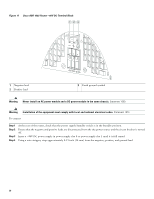
Read the safety warnings before you begin. Warning Never install an AC power module and a DC power module in the same chassis. Statement 1050 Warning Installation of the equipment must comply with local and national electrical codes. Statement 1074 Warning When installing or replacing the unit, the ground connection must always be made first and disconnected last. Statement 1046 Warning This equipment must be grounded. Never defeat the ground conductor or operate the equipment in the absence of a suitably installed ground conductor. Contact the appropriate electrical inspection authority or an electrician if you are uncertain that suitable grounding is available. Statement 1024 Warning This unit has two power supply connections. All connections must be removed to de-energize the unit. Statement 1028 Warning This product relies on the building's installation for short-circuit (overcurrent) protection. Ensure that the protective device is rated not greater than: AC power supplies for the Cisco Aggregation Services Routers: 120 VAC, 20A U.S. maximum. DC power supplies for the Cisco ASR 1006 Router: 50A U.S. maximum; Cisco ASR 1004 Router: 40A U.S. maximum: Cisco ASR 1002 Router: 30A (-48V) U.S. and 40A (+24V) U.S. maximum. Statement 1005 Figure 12 shows the AC power supply for the Cisco ASR 1002 Router. Figure 12 AC Power Supply for the Cisco ASR 1002 Router 12 34 5 6 0 OUTPUT INPUT FAN FAIL OK OK This unit might have more than one power supply connection. All connections must be removed to de-energize the unit. OUTPUT INPUT FAN FAIL OK OK This unit might have more than one power supply connection. All connections must be removed to de-energize the unit. 1 280288 8 7 1 Chassis ESD socket 2 AC power supply slot number 0 3 AC power supply On (I) /Off (O) switch 4 AC power supply LEDs 5 AC power supply fan 6 AC power supply captive installation screw 7 AC power supply slot number 1 8 AC power inlet Table 1 describes the AC power supply LEDs on the Cisco ASR 1002 Router. Table 1 Cisco ASR 1002 Router AC Power Supply LEDs 15
-
 1
1 -
2
-
3
-
4
-
5
-
6
-
7
-
8
-
9
-
 10
10 -
 11
11 -
 12
12 -
 13
13 -
 14
14 -
 15
15 -
 16
16 -
 17
17 -
 18
18 -
 19
19 -
 20
20 -
21
-
22
-
23
-
24
-
25
-
26
-
27
-
28
-
29
-
30
-
31
-
32
-
33
-
34
-
35
-
36
-
37
-
38
-
39
-
40
-
41
-
42
-
43
-
44
-
45
-
46
 |
 |