Cisco CISCO2509-CH Getting Started Guide - Page 20
Step 3, Bootup Script and Power-On Self Test
 |
UPC - 746320009506
View all Cisco CISCO2509-CH manuals
Add to My Manuals
Save this manual to your list of manuals |
Page 20 highlights
Figure 10 Mounting the Controller in a 19-Inch Rack 1 282086 1 #10-32 pan-head screws or #12-24 slotted head screws Step 3 Step 4 After the controller is mounted in the rack, perform the following tasks to complete the installation: • Connecting the Controller Console Port • Securing the Power Adapter Cable • Connecting to the Network For configuration instructions about using the CLI setup program, see the "Running the Bootup Script and Power-On Self Test" section on page 23. 20
-
 1
1 -
2
-
3
-
4
-
5
-
6
-
7
-
8
-
9
-
10
-
11
-
12
-
13
-
14
-
 15
15 -
 16
16 -
 17
17 -
 18
18 -
 19
19 -
 20
20 -
 21
21 -
 22
22 -
 23
23 -
 24
24 -
 25
25 -
26
-
27
-
28
-
29
-
30
-
31
-
32
-
33
-
34
-
35
-
36
-
37
-
38
-
39
-
40
-
41
-
42
-
43
-
44
-
45
-
46
-
47
-
48
-
49
-
50
-
51
-
52
-
53
-
54
-
55
-
56
 |
 |

20
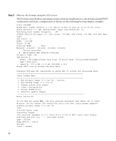
Figure 10
Mounting the Controller in a 19-Inch Rack
Step 3
After the controller is mounted in the rack, perform the following tasks to complete the
installation:
•
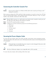
Connecting the Controller Console Port
•
Securing the Power Adapter Cable
•
Connecting to the Network
Step 4
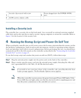
For configuration instructions about using the CLI setup program, see the
“Running the
Bootup Script and Power-On Self Test” section on page 23
.
1
#10-32 pan-head screws or #12-24 slotted head screws
1
282086