Cisco HGA9N Administration Guide - Page 10
Distance Calculation Examples, Table 1, Coverage Distance from Access Point to Client Devices - antenna
 |
UPC - 745883577392
View all Cisco HGA9N manuals
Add to My Manuals
Save this manual to your list of manuals |
Page 10 highlights
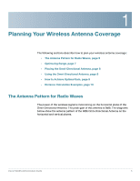
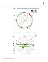
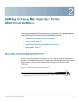
1 Distance Calculation Examples You can use the information in the tables below to determine how you want to place the Omni-Directional Antenna in relation to the access point to client device or between the two access points. As you can see, the higher the transmit data rate, the shorter the coverage distance. Therefore, when a client device moves further away from an access point, the data rate will fall back to a lower data rate. Table 1 Coverage Distance from Access Point to Client Devices Data Rate Distance 11 Mbps 0.88 km .55 miles 54 Mbps 0.12 km 0.078 miles Table 2 Coverage Distance from Access Point to Access Point Data Rate Distance 11 Mbps 2.49 km 1.56 miles 54 Mbps 0.35 km 0.22 miles To obtain these calculations, we inserted the specifications of the access point into the formula as described previously. We use 9dBi peak antenna gain and assume 0dBi antenna gain at the client device. Link budget is set to 10dB to include radio wave attenuations from different types of objects in the path (the actual value may vary). Cisco HGA9N Administration Guide 10
-
 1
1 -
2
-
3
-
4
-
 5
5 -
 6
6 -
 7
7 -
 8
8 -
 9
9 -
 10
10 -
 11
11 -
 12
12 -
 13
13 -
 14
14 -
 15
15 -
16
-
17
-
18
-
19
-
20
-
21
-
22
 |
 |