Cisco PIX 501 Quick Start Guide - Page 6
Check the LEDs - configure
 |
UPC - 746320551470
View all Cisco PIX 501 manuals
Add to My Manuals
Save this manual to your list of manuals |
Page 6 highlights
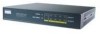
5 Check the LEDs CISCO PIX 501 F I R E WA L L POWER VPN TUNNEL LINK/ACT 100 MBPS 0 1234 61392 The LINK/ACT LED indicators on the front panel of the PIX Firewall are normally solid green when a link is established and flashing green when the ports are active. Each inside Ethernet interface (1 through 4) has two LEDs to indicate the operating speed and that the physical link is established. Note If all LEDs are operating as expected (see Table 1), this concludes the hardware installation. The pages that follow include instructions on running PDM and additional optional procedures. Table 1 PIX 501 LEDs LED POWER LINK/ACT State Description Green The device is powered on. Off The device is powered off. Flashing Network activity, such as Internet access, is present. green Green The correct cable is in use, and the connected equipment has power. Off No link is established. Tip If the LINK/ACT LED does not light up, you might be using the wrong type of cable. Try replacing the yellow (straight-through) Ethernet cable with the orange (crossover) Ethernet cable. VPN TUNNEL Green One or more IKE/IPSec VPN tunnels are active. Off No VPN tunnels are active. The default configuration does not include VPN. Thus, the VPN tunnel LED will only be enabled if VPN is added to your configuration and a VPN tunnel is then established. Also, the LED does not light up when PPTP/L2TP tunnels are established. 100 MBPS Green The interface is autonegotiated at 100-Mbps half or full duplex. Flashing The interface is functioning at 10-Mbps half or full duplex. green 6
-
 1
1 -
 2
2 -
 3
3 -
 4
4 -
 5
5 -
 6
6 -
 7
7 -
 8
8 -
 9
9 -
 10
10 -
 11
11 -
 12
12 -
13
-
14
-
15
-
16
-
17
-
18
-
19
-
20
 |
 |
