Cisco WS-C2960-48PST-S Hardware Installation Guide - Page 24
LEDs - poe
 |
View all Cisco WS-C2960-48PST-S manuals
Add to My Manuals
Save this manual to your list of manuals |
Page 24 highlights
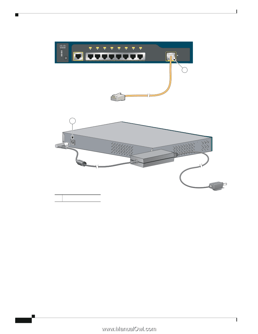
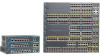
Front Panel Description Chapter 1 Product Overview Figure 1-21 Connecting Through a 10/100/1000 Port SYST STAT DPLX SPD 1x 2x 3x 4x 5x 6x 7x 8x CONSOLE MODE Catalyst 2960 Series 1 PoE INPUT 1 204644 Figure 1-22 1 Connecting Through an External AC Power Adapter 48V , 0.3 A 270433 LEDs 1 Power adapter port You can use the switch LEDs to monitor switch activity and its performance. Figure 1-23 shows the switch LEDs and the Mode button that you use to select one of the port modes. All LEDs are visible through the GUI management applications-Network Assistant for multiple switches and the device manager for a single switch. The switch software configuration guide describes how to use the CLI to configure and to monitor individual switches and switch clusters. Only the Catalyst 2960 PoE switches have a PoE LED. The four Catalyst 2960 8-port switches and these models do not have an RPS connector or an RPS LED: Catalyst 2960-24-S, Catalyst 2960-24TC-S, Catalyst 2960-48TT-S, Catalyst 2960-48TC-S. 1-14 Catalyst 2960 Switch Hardware Installation Guide OL-7075-09
-
 1
1 -
2
-
3
-
4
-
5
-
6
-
7
-
8
-
9
-
10
-
11
-
12
-
13
-
14
-
15
-
16
-
17
-
18
-
 19
19 -
 20
20 -
 21
21 -
 22
22 -
 23
23 -
 24
24 -
 25
25 -
 26
26 -
 27
27 -
 28
28 -
 29
29 -
30
-
31
-
32
-
33
-
34
-
35
-
36
-
37
-
38
-
39
-
40
-
41
-
42
-
43
-
44
-
45
-
46
-
47
-
48
-
49
-
50
-
51
-
52
-
53
-
54
-
55
-
56
-
57
-
58
-
59
-
60
-
61
-
62
-
63
-
64
-
65
-
66
-
67
-
68
-
69
-
70
-
71
-
72
-
73
-
74
-
75
-
76
-
77
-
78
-
79
-
80
-
81
-
82
-
83
-
84
-
85
-
86
-
87
-
88
-
89
-
90
-
91
-
92
-
93
-
94
-
95
-
96
-
97
-
98
-
99
-
100
-
101
-
102
-
103
-
104
-
105
-
106
-
107
-
108
 |
 |