Cisco WS-C3560-24PS-E Hardware Installation Guide - Page 95
Dual-Purpose Ports, Console Port, B-4, Copper SFP Module RJ-45 Connector, 100/1000 Port Pinouts
 |
View all Cisco WS-C3560-24PS-E manuals
Add to My Manuals
Save this manual to your list of manuals |
Page 95 highlights
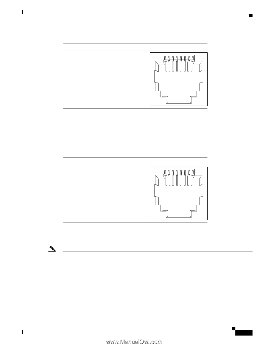
Appendix B Connector and Cable Specifications Connector Specifications Figure B-4 Pin 1 2 3 4 5 6 7 8 Copper SFP Module RJ-45 Connector Label 12345678 TP0+ TP0TP1+ TP2+ TP2TP1TP3+ TP3- 60915 Dual-Purpose Ports The Ethernet port on a dual-purpose port uses standard RJ-45 connectors. Figure B-5 shows the pinouts. Figure B-5 Pin 1 2 3 4 5 6 7 8 10/100/1000 Port Pinouts Label TP0+ TP0TP1+ TP2+ TP2TP1TP3+ TP3- 12345678 60915 The SFP module slot on a dual-purpose port uses SFP modules for fiber-optic and copper uplink ports. See the Catalyst 3560 release notes for a list of supported SFP modules. Note The auto-MDIX feature is enabled by default. For configuration information for this feature, see the switch software configuration guide or the switch command reference. Console Port The console port uses an 8-pin RJ-45 connector, described in Table B-2 and Table B-3. The RJ-45-to-DB-9 adapter cable connects the console port of the switch to a console PC. You need an RJ-45-to-DB-25 female DTE adapter (ACS-DSBUASYN=) to connect the switch console port to a terminal. For console port and adapter pinout information, see Table B-2 and Table B-3. OL-6337-07 Catalyst 3560 Switch Hardware Installation Guide B-3
-
 1
1 -
2
-
3
-
4
-
5
-
6
-
7
-
8
-
9
-
10
-
11
-
12
-
13
-
14
-
15
-
16
-
17
-
18
-
19
-
20
-
21
-
22
-
23
-
24
-
25
-
26
-
27
-
28
-
29
-
30
-
31
-
32
-
33
-
34
-
35
-
36
-
37
-
38
-
39
-
40
-
41
-
42
-
43
-
44
-
45
-
46
-
47
-
48
-
49
-
50
-
51
-
52
-
53
-
54
-
55
-
56
-
57
-
58
-
59
-
60
-
61
-
62
-
63
-
64
-
65
-
66
-
67
-
68
-
69
-
70
-
71
-
72
-
73
-
74
-
75
-
76
-
77
-
78
-
79
-
80
-
81
-
82
-
83
-
84
-
85
-
86
-
87
-
88
-
89
-
 90
90 -
 91
91 -
 92
92 -
 93
93 -
 94
94 -
 95
95 -
 96
96 -
 97
97 -
 98
98 -
 99
99 -
 100
100 -
101
-
102
-
103
-
104
-
105
-
106
-
107
-
108
-
109
-
110
-
111
-
112
-
113
-
114
-
115
-
116
-
117
-
118
-
119
-
120
 |
 |