Cisco WS-C4003-RF Hardware Maintenance Manual - Page 60
Making Network Connections, Making Token Ring Connections
 |
View all Cisco WS-C4003-RF manuals
Add to My Manuals
Save this manual to your list of manuals |
Page 60 highlights
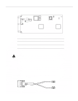
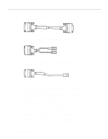
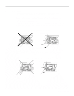
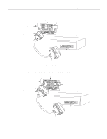
Making Network Connections Follow these steps to connect your system's console port to a terminal: Step 1 Ensure that your site meets the site preparation requirements described in the section "Preparing to Make Connections" in the chapter "Preparing for Installation." Step 2 If you have not already done so, unpack your system referring to the section "Inspecting the System" in the chapter "Preparing for Installation." Step 3 Attach your terminal to the EIA/TIA-232 console port with a console cable. Note Flow control is not possible on the console port; however, you can specify padding for output characters with the EXEC command terminal [no] padding, which sets character padding on the current terminal line. For details on specifying padding, refer to the appropriate Cisco IOS publication. Making Network Connections Make the network connections by attaching the network interface cables to the appropriate connector on the network processor modules. If more than one network processor module of a given interface type is used in a system, the lowest unit number of a given interface type is the module closest to the power supply. (See the sections "Slot Numbering" and "Unit Numbering" in the chapter "Preparing for Installation.") Making Token Ring Connections Step 1 Attach the network processor module connector labeled Token Ring to the 9-pin D-type connector of the Token Ring cable. (See Figure 3-1.) Figure 3-1 Making Token Ring Connections Token Ring module Router (rear view) DB-9 connector TOKEN RING NP-1RV2 IN-RING 16MBPS AUX H2539 Step 2 Attach the IEEE 802.5 connector to your media attachment unit (MAU). When all the network connections are complete, proceed to the section "Making Final Connections to the Router." 3-2 Cisco 4000 Series Hardware Installation and Maintenance
-
 1
1 -
2
-
3
-
4
-
5
-
6
-
7
-
8
-
9
-
10
-
11
-
12
-
13
-
14
-
15
-
16
-
17
-
18
-
19
-
20
-
21
-
22
-
23
-
24
-
25
-
26
-
27
-
28
-
29
-
30
-
31
-
32
-
33
-
34
-
35
-
36
-
37
-
38
-
39
-
40
-
41
-
42
-
43
-
44
-
45
-
46
-
47
-
48
-
49
-
50
-
51
-
52
-
53
-
54
-
 55
55 -
 56
56 -
 57
57 -
 58
58 -
 59
59 -
 60
60 -
 61
61 -
 62
62 -
 63
63 -
 64
64 -
 65
65 -
66
-
67
-
68
-
69
-
70
-
71
-
72
-
73
-
74
-
75
-
76
-
77
-
78
-
79
-
80
-
81
-
82
-
83
-
84
-
85
-
86
-
87
-
88
-
89
-
90
-
91
-
92
-
93
-
94
-
95
-
96
-
97
-
98
-
99
-
100
-
101
-
102
-
103
-
104
-
105
-
106
-
107
-
108
-
109
-
110
-
111
-
112
-
113
-
114
-
115
-
116
-
117
-
118
-
119
-
120
-
121
-
122
-
123
-
124
-
125
-
126
-
127
-
128
-
129
-
130
-
131
-
132
-
133
-
134
-
135
-
136
-
137
-
138
-
139
-
140
-
141
-
142
-
143
 |
 |
