Cisco WS-C4003-RF Hardware Maintenance Manual - Page 78
Wiring the DC-Input Power Supply
 |
View all Cisco WS-C4003-RF manuals
Add to My Manuals
Save this manual to your list of manuals |
Page 78 highlights
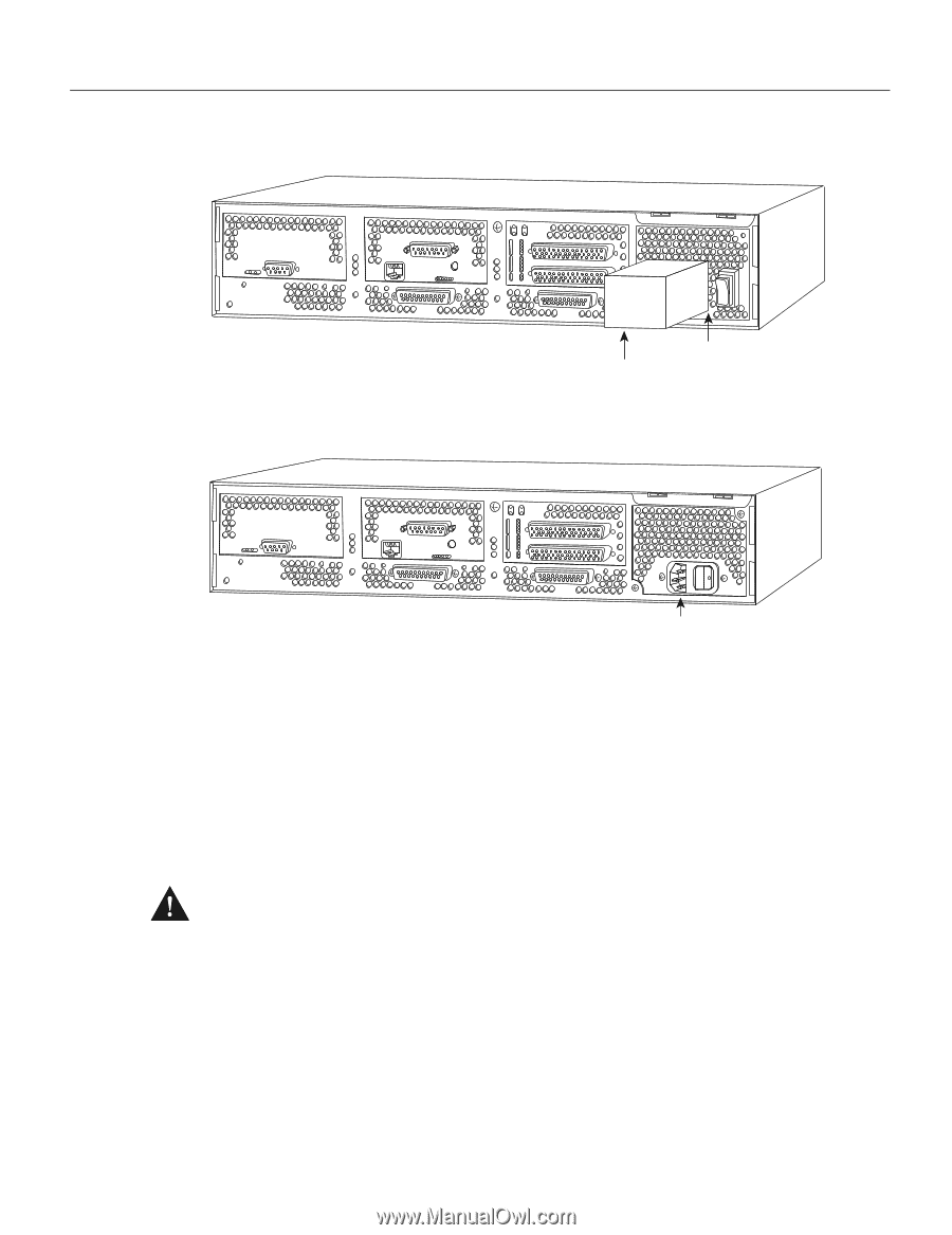
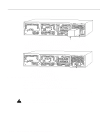
H2274 H2273 Connecting Routers with a DC-Input Power Supply Figure 3-13 Cisco 4000 Series DC-Input Power Supply-Rear View DC power supply Terminal block cover Figure 3-14 Cisco 4000 Series AC-Input Power Supply-Rear View AC power supply Wiring the DC-Input Power Supply Figure 3-15 shows the Cisco 4000 DC-input power supply terminal block. Follow these procedures for wiring the terminal block. Step 1 Feed the wires through the rubber grommet in the terminal block cover. Step 2 Attach the appropriate lugs at the wire end of the power supply cord. Step 3 Wire the DC-input power supply to the terminal block as shown in Figure 3-15. The proper wiring sequence is ground to ground, positive to positive, and negative to negative. Caution Do not overtorque the terminal block captive thumbscrew or terminal block contact screws. The recommended torque is 8.2 ± 0.4 inch-lb. 3-20 Cisco 4000 Series Hardware Installation and Maintenance
-
 1
1 -
2
-
3
-
4
-
5
-
6
-
7
-
8
-
9
-
10
-
11
-
12
-
13
-
14
-
15
-
16
-
17
-
18
-
19
-
20
-
21
-
22
-
23
-
24
-
25
-
26
-
27
-
28
-
29
-
30
-
31
-
32
-
33
-
34
-
35
-
36
-
37
-
38
-
39
-
40
-
41
-
42
-
43
-
44
-
45
-
46
-
47
-
48
-
49
-
50
-
51
-
52
-
53
-
54
-
55
-
56
-
57
-
58
-
59
-
60
-
61
-
62
-
63
-
64
-
65
-
66
-
67
-
68
-
69
-
70
-
71
-
72
-
 73
73 -
 74
74 -
 75
75 -
 76
76 -
 77
77 -
 78
78 -
 79
79 -
 80
80 -
 81
81 -
 82
82 -
 83
83 -
84
-
85
-
86
-
87
-
88
-
89
-
90
-
91
-
92
-
93
-
94
-
95
-
96
-
97
-
98
-
99
-
100
-
101
-
102
-
103
-
104
-
105
-
106
-
107
-
108
-
109
-
110
-
111
-
112
-
113
-
114
-
115
-
116
-
117
-
118
-
119
-
120
-
121
-
122
-
123
-
124
-
125
-
126
-
127
-
128
-
129
-
130
-
131
-
132
-
133
-
134
-
135
-
136
-
137
-
138
-
139
-
140
-
141
-
142
-
143
 |
 |