Cisco WS-C4948 Installation Guide - Page 34
Power Supplies - 10ge x2
 |
UPC - 746320908892
View all Cisco WS-C4948 manuals
Add to My Manuals
Save this manual to your list of manuals |
Page 34 highlights
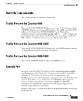
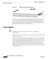
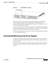
130085 Switch Components Chapter 1 Product Overview Figure 1-8 Airflow (Catalyst 4948-10GE shown) PS1 PS2 FAN STATUS 1 16 17 32 33 Catalyst WS-C4948 10GE X2-1 X2-2 CON 48 MGT There are four fans in the fan tray. If an individual fan fails, the other fans continue to run. Sensors monitor the internal air temperatures. The number of fans in operation and their speed varies according to the internal temperature for the quietest operation possible. If the air temperature exceeds a desired threshold, the environmental monitor displays warning messages. Power Supplies Note For complete power specifications for the switch, see Appendix A, "Specifications." The Catalyst 4900 series switches have two redundant internal 300 W AC or 300 W DC power supplies. The internal power supplies have individual power cords and status LEDs (PS1 and PS2 on the front panel). There are also LEDs on the power supplies that show status for the input (Input OK) and output (Output OK) currents. A power cord is used to connect the power supplies to the site power source. There is a power switch on the AC power supplies; AC power is present when a power cord is plugged into a power supply and the switch is set to the On position. DC power supplies do not have an on/off switch and do not provide a cable for connection to a DC power source. 1-12 Catalyst 4900 Series Switch Installation Guide 78-18039-02
-
 1
1 -
2
-
3
-
4
-
5
-
6
-
7
-
8
-
9
-
10
-
11
-
12
-
13
-
14
-
15
-
16
-
17
-
18
-
19
-
20
-
21
-
22
-
23
-
24
-
25
-
26
-
27
-
28
-
 29
29 -
 30
30 -
 31
31 -
 32
32 -
 33
33 -
 34
34 -
 35
35 -
 36
36 -
 37
37 -
 38
38 -
 39
39 -
40
-
41
-
42
-
43
-
44
-
45
-
46
-
47
-
48
-
49
-
50
-
51
-
52
-
53
-
54
-
55
-
56
-
57
-
58
-
59
-
60
-
61
-
62
-
63
-
64
-
65
-
66
-
67
-
68
-
69
-
70
-
71
-
72
-
73
-
74
-
75
-
76
-
77
-
78
-
79
-
80
-
81
-
82
-
83
-
84
-
85
-
86
-
87
-
88
-
89
-
90
-
91
-
92
-
93
-
94
-
95
-
96
-
97
-
98
-
99
-
100
-
101
-
102
-
103
-
104
-
105
-
106
-
107
-
108
-
109
-
110
-
111
-
112
-
113
-
114
-
115
-
116
-
117
-
118
-
119
-
120
-
121
-
122
-
123
-
124
-
125
-
126
-
127
-
128
-
129
-
130
-
131
-
132
-
133
-
134
-
135
-
136
-
137
-
138
-
139
-
140
-
141
-
142
 |
 |
