Cisco WS-C4948 Installation Guide - Page 55
Connecting AC Power to the Switch - 10ge power supply
 |
UPC - 746320908892
View all Cisco WS-C4948 manuals
Add to My Manuals
Save this manual to your list of manuals |
Page 55 highlights
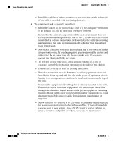
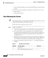
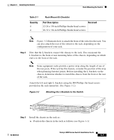
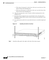
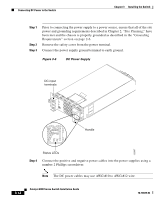
Chapter 3 Installing the Switch Connecting AC Power to the Switch Figure 3-4 Installing the Cable Guide 130089 PS1 PS2 FAN STATUS 1 16 17 32 33 Catalyst WS-C4948 10GE X2-1 X2-2 CON 48 MGT Step 5 Do not connect the power cord at this time. Proceed to the "Connecting AC Power to the Switch" section on page 3-9. Connecting AC Power to the Switch Follow these steps and warnings when connecting power to a Catalyst 4900 series switch: Step 1 Prior to connecting the power supply to a power source, ensure that all of the site power and grounding requirements described in Chapter 2, "Site Planning," have been met and the chassis is properly grounded as described in the "Grounding Requirements" section on page 2-6. Warning The plug-socket combination must be accessible at all times, because it serves as the main disconnecting device. Statement 1019 Step 2 Plug the power cords into the power supplies. (Figure 3-6 shows plug locations.) 78-18039-02 Catalyst 4900 Series Switch Installation Guide 3-9
-
 1
1 -
2
-
3
-
4
-
5
-
6
-
7
-
8
-
9
-
10
-
11
-
12
-
13
-
14
-
15
-
16
-
17
-
18
-
19
-
20
-
21
-
22
-
23
-
24
-
25
-
26
-
27
-
28
-
29
-
30
-
31
-
32
-
33
-
34
-
35
-
36
-
37
-
38
-
39
-
40
-
41
-
42
-
43
-
44
-
45
-
46
-
47
-
48
-
49
-
 50
50 -
 51
51 -
 52
52 -
 53
53 -
 54
54 -
 55
55 -
 56
56 -
 57
57 -
 58
58 -
 59
59 -
 60
60 -
61
-
62
-
63
-
64
-
65
-
66
-
67
-
68
-
69
-
70
-
71
-
72
-
73
-
74
-
75
-
76
-
77
-
78
-
79
-
80
-
81
-
82
-
83
-
84
-
85
-
86
-
87
-
88
-
89
-
90
-
91
-
92
-
93
-
94
-
95
-
96
-
97
-
98
-
99
-
100
-
101
-
102
-
103
-
104
-
105
-
106
-
107
-
108
-
109
-
110
-
111
-
112
-
113
-
114
-
115
-
116
-
117
-
118
-
119
-
120
-
121
-
122
-
123
-
124
-
125
-
126
-
127
-
128
-
129
-
130
-
131
-
132
-
133
-
134
-
135
-
136
-
137
-
138
-
139
-
140
-
141
-
142
 |
 |
