Cisco WS-X4448-GB-RJ45 Hardware Maintenance Manual - Page 59
Installing the Router, Rack-Mount and Wall-Mount Procedures Overview, Making Console Port
 |
UPC - 746320566030
View all Cisco WS-X4448-GB-RJ45 manuals
Add to My Manuals
Save this manual to your list of manuals |
Page 59 highlights
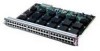
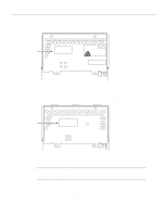
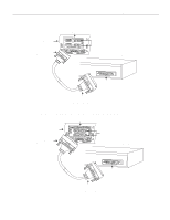
CHAPTER 3 Installing the Router This chapter describes the tasks you must perform to install your system. Sections of this chapter follow: • Rack-Mount and Wall-Mount Procedures Overview • Making Console Port Connections • Making Network Connections • Connecting Routers with a DC-Input Power Supply • Making Final Connections to the Router The router ships with optional rubber "feet." For a desktop or wall-mounted chassis, install the feet to provide adequate spacing between the chassis and the supporting surface for proper ventilation. For a rack-mounted chassis, do not install the rubber feet if the chassis is to be mounted directly above another chassis in the same rack. Rack-Mount and Wall-Mount Procedures Overview The router system has three mounting options: standard 19-inch rack mount, telco rack mount, or wall mount. The procedures for the different mounting options involve removing the front panel and component tray from the chassis shell and then installing the empty shell in position before reinserting the component tray. The optional rack-mount/wall-mount kit ships with its own set of instructions for rack and wall mounting. If you are planning to rack-mount or wall-mount the router, do so before making the network and power connections while following the procedures described in the separate rack-mount/wall-mount publication included with the rack-mount kit. Making Console Port Connections To prepare for initial startup and configuration, you must connect an EIA/TIA-232 cable between an ASCII terminal and the system console port, and you must attach the power cord. The console port and auxiliary ports have jackscrews to accommodate cables with thumbscrews. If your cable connection requires it, the jackscrews can be removed. Installing the Router 3-1
-
 1
1 -
2
-
3
-
4
-
5
-
6
-
7
-
8
-
9
-
10
-
11
-
12
-
13
-
14
-
15
-
16
-
17
-
18
-
19
-
20
-
21
-
22
-
23
-
24
-
25
-
26
-
27
-
28
-
29
-
30
-
31
-
32
-
33
-
34
-
35
-
36
-
37
-
38
-
39
-
40
-
41
-
42
-
43
-
44
-
45
-
46
-
47
-
48
-
49
-
50
-
51
-
52
-
53
-
 54
54 -
 55
55 -
 56
56 -
 57
57 -
 58
58 -
 59
59 -
 60
60 -
 61
61 -
 62
62 -
 63
63 -
 64
64 -
65
-
66
-
67
-
68
-
69
-
70
-
71
-
72
-
73
-
74
-
75
-
76
-
77
-
78
-
79
-
80
-
81
-
82
-
83
-
84
-
85
-
86
-
87
-
88
-
89
-
90
-
91
-
92
-
93
-
94
-
95
-
96
-
97
-
98
-
99
-
100
-
101
-
102
-
103
-
104
-
105
-
106
-
107
-
108
-
109
-
110
-
111
-
112
-
113
-
114
-
115
-
116
-
117
-
118
-
119
-
120
-
121
-
122
-
123
-
124
-
125
-
126
-
127
-
128
-
129
-
130
-
131
-
132
-
133
-
134
-
135
-
136
-
137
-
138
-
139
-
140
-
141
-
142
-
143
 |
 |
