Cisco WS-X4908-10GE= Hardware Maintenance Manual - Page 28
Site Log, Required Tools and Equipment - ethernet switch
 |
UPC - 882658171956
View all Cisco WS-X4908-10GE= manuals
Add to My Manuals
Save this manual to your list of manuals |
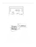
Page 28 highlights
Site Log Site Log The Site Log provides a historical record of all actions relevant to the router. Keep it in a common place near the chassis where anyone who performs tasks has access to it. Use the Installation Checklist to verify steps in the installation and maintenance of your router. Site Log entries might include the following: • Installation progress-Make a copy of the Installation Checklist and insert it into the Site Log. Make entries as each procedure is completed. • Upgrades and removal or replacement procedures-Use the Site Log as a record of ongoing router maintenance and expansion history. Each time a procedure is performed on the router, update the Site Log to reflect the following: - Additional network processor modules - Removal or replacement of network processor modules - Configuration changes - Maintenance schedules and requirements - Maintenance procedures performed - Intermittent problems - Related comments Required Tools and Equipment You need the following tools and equipment for the installation of the router: • ESD cord and wrist strap • Screwdrivers, Number 1 and Number 2 Phillips • One serial port adapter cable for each serial port to connect the port with the remote device or network In addition, you might need the following additional external equipment: • Data service unit (DSU) to connect each serial port to an external network. • To connect a serial port to a T1 network, you need a T1 channel service unit/data service unit (CSU/DSU) that converts the High-Level Data Link Control (HDLC) synchronous serial data stream into a T1 data stream with the correct framing and ones density. (Some telephone systems require a minimum number of 1 bits per time unit in a data stream, called ones density.) Several T1 CSU/DSU devices are available as additional equipment, and most provide either a V.35, EIA/TIA-449, or EIA-530 electrical interface. • Ethernet transceiver. • Token Ring media attachment unit (MAU). • Optical bypass switch or concentrator for multimode Fiber Distributed Data Interface (FDDI) connections. 2-6 Cisco 4000 Series Hardware Installation and Maintenance
-
 1
1 -
2
-
3
-
4
-
5
-
6
-
7
-
8
-
9
-
10
-
11
-
12
-
13
-
14
-
15
-
16
-
17
-
18
-
19
-
20
-
21
-
22
-
 23
23 -
 24
24 -
 25
25 -
 26
26 -
 27
27 -
 28
28 -
 29
29 -
 30
30 -
 31
31 -
 32
32 -
 33
33 -
34
-
35
-
36
-
37
-
38
-
39
-
40
-
41
-
42
-
43
-
44
-
45
-
46
-
47
-
48
-
49
-
50
-
51
-
52
-
53
-
54
-
55
-
56
-
57
-
58
-
59
-
60
-
61
-
62
-
63
-
64
-
65
-
66
-
67
-
68
-
69
-
70
-
71
-
72
-
73
-
74
-
75
-
76
-
77
-
78
-
79
-
80
-
81
-
82
-
83
-
84
-
85
-
86
-
87
-
88
-
89
-
90
-
91
-
92
-
93
-
94
-
95
-
96
-
97
-
98
-
99
-
100
-
101
-
102
-
103
-
104
-
105
-
106
-
107
-
108
-
109
-
110
-
111
-
112
-
113
-
114
-
115
-
116
-
117
-
118
-
119
-
120
-
121
-
122
-
123
-
124
-
125
-
126
-
127
-
128
-
129
-
130
-
131
-
132
-
133
-
134
-
135
-
136
-
137
-
138
-
139
-
140
-
141
-
142
-
143
 |
 |