Cisco WS-X4908-10GE= Hardware Maintenance Manual - Page 77
Connecting Routers with a DC-Input Power Supply, Con the ATM NSAP address
 |
UPC - 882658171956
View all Cisco WS-X4908-10GE= manuals
Add to My Manuals
Save this manual to your list of manuals |
Page 77 highlights
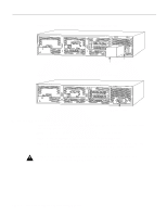
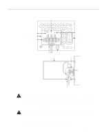
Connecting Routers with a DC-Input Power Supply Step 6 Configure the ATM NSAP address: Router(config-if)# atm nsap-address nsap-addrr where an example of nsap-addr could be: AB.CDEF.01.234567.890A.BCDE.F012.3456.7890.1234.12 Step 7 Assign the appropriate map-list to the interface: Router(config-map-list)# map-group list2 Step 8 Enable the interface: Router(config-if)# no shut Step 9 Create the mapping of protocol addresses to ATM NSAP addresses, as follows: Router(config-if)# map-list list2 Router(config-map-list)# ip 2.1.1.2 nsap-addr nsap-addr br Router(config-map-list)# ip 2.1.1.3 nsap-addr nsap-addr br Step 10 To complete the configuration, enter Ctrl-Z. Step 11 Write the new configuration to memory: Router# write memory Step 12 Exit the privileged level and return to the user level: Router# disable Connecting Routers with a DC-Input Power Supply Warning Before conducting any of the following procedures, ensure that power is removed from the DC circuit. To ensure that all power is OFF, locate the circuit breaker on the panel board that services the DC circuit, switch the circuit breaker to the OFF position, and tape the switch handle of the circuit breaker in the OFF position. Note The installation must comply with the 1993 National Electric Code (NEC) and other applicable codes. If you ordered a Cisco 4000 series router with a DC-input power supply, follow the directions in this section for proper wiring. For identification purposes, Figure 3-13 shows a Cisco 4000 series router with a DC-input power supply; Figure 3-14 shows a Cisco 4000 series router with an AC-input power supply. Installing the Router 3-19
-
 1
1 -
2
-
3
-
4
-
5
-
6
-
7
-
8
-
9
-
10
-
11
-
12
-
13
-
14
-
15
-
16
-
17
-
18
-
19
-
20
-
21
-
22
-
23
-
24
-
25
-
26
-
27
-
28
-
29
-
30
-
31
-
32
-
33
-
34
-
35
-
36
-
37
-
38
-
39
-
40
-
41
-
42
-
43
-
44
-
45
-
46
-
47
-
48
-
49
-
50
-
51
-
52
-
53
-
54
-
55
-
56
-
57
-
58
-
59
-
60
-
61
-
62
-
63
-
64
-
65
-
66
-
67
-
68
-
69
-
70
-
71
-
 72
72 -
 73
73 -
 74
74 -
 75
75 -
 76
76 -
 77
77 -
 78
78 -
 79
79 -
 80
80 -
 81
81 -
 82
82 -
83
-
84
-
85
-
86
-
87
-
88
-
89
-
90
-
91
-
92
-
93
-
94
-
95
-
96
-
97
-
98
-
99
-
100
-
101
-
102
-
103
-
104
-
105
-
106
-
107
-
108
-
109
-
110
-
111
-
112
-
113
-
114
-
115
-
116
-
117
-
118
-
119
-
120
-
121
-
122
-
123
-
124
-
125
-
126
-
127
-
128
-
129
-
130
-
131
-
132
-
133
-
134
-
135
-
136
-
137
-
138
-
139
-
140
-
141
-
142
-
143
 |
 |