Coby TFDVD1995 User Manual - Page 8
Unit View - remote control
 |
UPC - 716829931950
View all Coby TFDVD1995 manuals
Add to My Manuals
Save this manual to your list of manuals |
Page 8 highlights
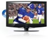
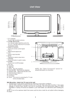
Unit View 1 9 10 11 12 13 14 2 4 5 6 7 8 3 1. TFT SCREEN Present high resolution pictures 2. POWER INDICATOR The indicator lights bright blue when the TV is on, it will dim when the TV is turned off (standby mode). 3. REMOTE SENSOR 9 Sense the remote control signal. 4. VOL+/- Adjust sound output level. 5. CH+/- Press to skip channels. 6. MENU 10 Display the system setup menu. 7. SOURCE Press this button to switch modes. 8. POWER 11 Press to turn on/off the player. 9. Disc Slot 10. Card Slot 11. USB Port 12. STOP - Stop disc playback. 13. PLAY/PAUSE - Start/hold disc playback. 14. OPEN/CLOSE - Open/close the disc room. 15. Wall Mounting Thread X 4 16. Connector Panel 17. Unit Stand 18. Screw - This screw is connecting the TV case to the unit stand-base. NOTE: See "Cable Connections" section for detailed description on connectors. Wall Mounting - Attach the TV case to the wall • Separate the TV case and the stand-base by removing screws before installation. • Use the VESA standard mountings to fix the unit on the wall. Take care when mounting, it may cause damage or serious injury should it fall from its mountings. See the Specification page for VESA informaiton. A variety of mounts are available in your local retailer, see instructions when installing the unit. NOTE: 10 mm is the maximum depth that screws could be driven inside the unit cabinet without damaging the player. 3
-
 1
1 -
2
-
 3
3 -
 4
4 -
 5
5 -
 6
6 -
 7
7 -
 8
8 -
 9
9 -
 10
10 -
 11
11 -
 12
12 -
 13
13 -
14
-
15
-
16
-
17
-
18
-
19
-
20
-
21
-
22
-
23
-
24
-
25
-
26
-
27
-
28
-
29
-
30
-
31
 |
 |