Coby TFTV1525 User Manual - Page 9
Unit View - specifications
 |
UPC - 716829921555
View all Coby TFTV1525 manuals
Add to My Manuals
Save this manual to your list of manuals |
Page 9 highlights
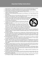
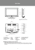
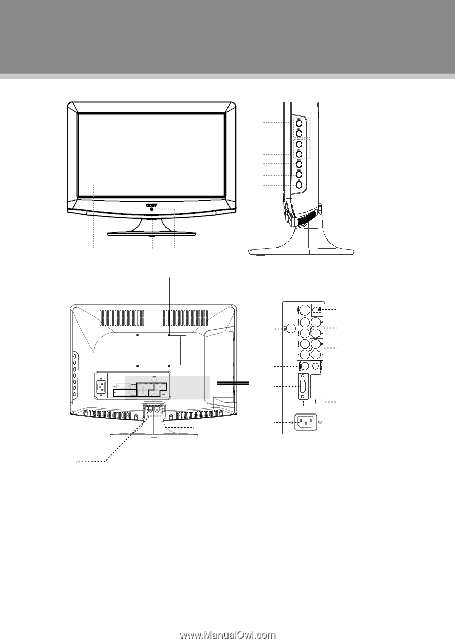
Unit View 4 5 6 7 8 1 2 3 75mm < > > < 12 9 13 75mm 14 10 > 11 15 16 Unit Stand Screw x 2 1. TFT SCREEN 2. POWER INDICATOR 3. REMOTE SENSOR 4. VOLUME-/+ 5. CH-/+ 6. MENU 7. MODE 8. POWER 9. ANTENNA JACK 10. COAXIAL 11. HDMI 12. HEADPHONE OUTPUT 13. VIDEO/S-VIDEO INPUT 14. COMPONENT INPUT 15. VGA INPUT 16. POWER JACK Wall Mounting - Attach the TV case to the wall •• Release screws and take apart the unit case and the unit stand. •• Use the VESA standard mountings to fix the unit on the wall. Take care when mounting, it may cause damage or serious injury should it fall from its mountings. See the Specification page for VESA informaiton. 3
-
 1
1 -
2
-
3
-
 4
4 -
 5
5 -
 6
6 -
 7
7 -
 8
8 -
 9
9 -
 10
10 -
 11
11 -
 12
12 -
 13
13 -
 14
14 -
15
-
16
-
17
-
18
-
19
-
20
-
21
 |
 |
3
2
1
3
4
5
6
7
8
Screw x 2
Unit Stand
<
>
<
>
75mm
75mm
9
10
11
12
13
14
15
>
16
Wall Mounting - Attach the TV case to the wall
Release screws and take apart the unit case and the unit stand.
•
Use the VESA standard mountings to fix the unit on the wall. Take care when mounting, it may cause
•
damage or serious injury should it fall from its mountings. See the Specification page for VESA
informaiton.
1. TFT SCREEN
2. POWER INDICATOR
3. REMOTE SENSOR
4. VOLUME-/+
5. CH-/+
6. MENU
7. MODE
8. POWER
9. ANTENNA JACK
10. COAXIAL
11. HDMI
12. HEADPHONE
OUTPUT
13. VIDEO/S-VIDEO INPUT
14. COMPONENT INPUT
15. VGA INPUT
16. POWER JACK
Unit View