Compaq 307560-001 Compaq ProLiant 2500 Server Technology - Page 6
Security
 |
UPC - 743172470379
View all Compaq 307560-001 manuals
Add to My Manuals
Save this manual to your list of manuals |
Page 6 highlights
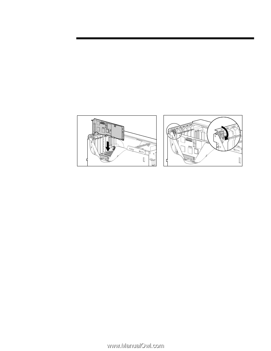
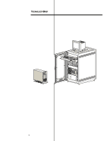
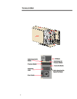
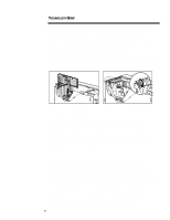
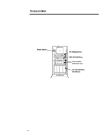
201A/1196 TECHNOLOGY BRIEF (cont.) ... Adding or replacing a processor in the ProLiant 2500 simply requires opening the quick release lever, sliding out the processor board, sliding in a new processor board, and closing the quick release lever. Since main memory in the ProLiant 2500 is mounted on the processor board, adding or changing out main memory is equally simple. The slide-out processor module provides ready access to memory slots. A used DIMM (dual in-line memory module) pulls readily from its slot; and with a slight push, a new pluggable DIMM seats securely in its place. Access to the I/O board for servicing PCI and EISA cards is also quick and tool-less. In the ProLiant 2500 tower model, access to the cards is from the top. In the rack model, access is from the side to provide equal visibility. The I/O cards slide smoothly into the expansion slots on the I/O board. A Compaq-designed rotating latch locks each card securely into place in the option card bay and also serves as a quick release for easy removal and replacement of cards (Figure 4). CZR-037a.eps CZR-052.eps Figure 4. In a ProLiant 2500 tower model, PCI and EISA cards slide into the I/O slots from the top (left). A unique rotating latch secures each card (right). A single quick-release knob provides easy access to the system fan, which is mounted perpendicular to the back panel and exhausts through an outlet below the fan assembly itself (see Figure 3). The power supply is mounted with four screws that can be easily removed. With its compact 5U chassis, the ProLiant 2500 provides for improved server density in rack environments. Customers can stack up to eight ProLiant 2500 servers in a single 42U Compaq rack cabinet. By comparison, the 7U chassis of the ProLiant 1500 Server permits stacking six servers in a 42U rack cabinet. With the improved density, installation of the ProLiant 2500 becomes a one- or two-man task as opposed to a two- or three-man task; thus, the increased density saves customers both space and maintenance costs. Security While high serviceability requires easy access to server components, security of data and equipment is paramount. The ProLiant 2500 housing and chassis design achieves both. In a rack configuration, access to the system is controlled by two key locks: one on the front door and a second on the rear door of the rack cabinet. In the tower model, a single key lock on the front bezel controls access to the system. The top, side, and back panels of the housing slide onto the chassis and interlock. The hinged front bezel closes over the edges of the top and side panel, securing them. A simple half turn of the key lock opens or locks the front bezel for the first line of defense against unauthorized access to the hard drives and other components (Figure 5). The ProLiant 2500 also provides an optional, second level of security for rear-mounted components. The ProLiant 2500 comes equipped with three set screws (Figure 6) that can be used to lock the processor module, the I/O module, and the fan in place. By simply moving these screws from their initial position and placing them in the three holes shown in Figure 6, the customer can secure the rear-access modules against quick release and removal. 6
-
 1
1 -
 2
2 -
 3
3 -
 4
4 -
 5
5 -
 6
6 -
 7
7 -
 8
8 -
 9
9 -
 10
10 -
 11
11 -
 12
12 -
13
-
14
-
15
-
16
-
17
-
18
 |
 |