Compaq 307560-001 Compaq ProLiant 2500 Server Technology - Page 7
To prevent someone from turning off the power to the server, this sliding switch cover
 |
UPC - 743172470379
View all Compaq 307560-001 manuals
Add to My Manuals
Save this manual to your list of manuals |
Page 7 highlights
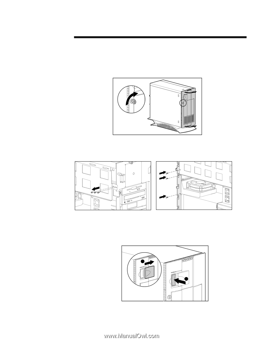
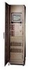
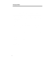
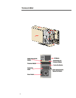
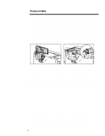
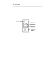
201A/1196 TECHNOLOGY BRIEF (cont.) ... The ProLiant 2500 tower model also includes a Compaq-designed security system for the server power switch. The power switch is mounted on the chassis, behind the front bezel. When the front bezel is locked into place, the power switch is accessible by means of small, sliding cover (Figure 7). To prevent someone from turning off the power to the server, this sliding switch cover can be shut and locked using a single screw on the inside of the front bezel. CZR-002.EPS Figure 5. A key lock on the front bezel of the Compaq ProLiant 2500 Server secures data and internal components from unauthorized access. CZR-051a.eps CZR-051.eps Figure 6. Three set screws mounted on the chassis under the side panel are provided for optional use to lock rear-mounted, quick release modules in place. If moved to the indicated positions, these three screws will secure the processor module, the I/O module, and the fan against quick release and removal. 1 2 CZR-041.EPS Figure 7. The sliding cover for the ProLiant 2500 power switch can be locked from the inside. 7
-
 1
1 -
 2
2 -
 3
3 -
 4
4 -
 5
5 -
 6
6 -
 7
7 -
 8
8 -
 9
9 -
 10
10 -
 11
11 -
 12
12 -
13
-
14
-
15
-
16
-
17
-
18
 |
 |