Compaq 500B Maintenance & Service Guide: Compaq 500B and 505B Minitower Bu
Compaq 500B - Microtower PC Manual
 |
View all Compaq 500B manuals
Add to My Manuals
Save this manual to your list of manuals |
Compaq 500B manual content summary:
- Compaq 500B | Maintenance & Service Guide: Compaq 500B and 505B Minitower Bu - Page 1
Maintenance & Service Guide Compaq 500B and 505B Minitower Business PC - Compaq 500B | Maintenance & Service Guide: Compaq 500B and 505B Minitower Bu - Page 2
HP products and services are set forth in the express warranty statements accompanying such products and services. Nothing herein should be construed as constituting an additional warranty. HP -Packard Company. Compaq 500B and 505B Minitower Business PC First Edition (September 2009) Document - Compaq 500B | Maintenance & Service Guide: Compaq 500B and 505B Minitower Bu - Page 3
About This Book WARNING! Text set off in this manner indicates that failure to follow directions could result in bodily harm or loss of life. CAUTION: Text set off in this manner indicates that failure to follow directions could result in damage to equipment or loss of information. NOTE: Text set - Compaq 500B | Maintenance & Service Guide: Compaq 500B and 505B Minitower Bu - Page 4
iv About This Book - Compaq 500B | Maintenance & Service Guide: Compaq 500B and 505B Minitower Bu - Page 5
Assembly 31 Power Switch/LED Assembly ...32 System Fan ...33 Heat sink assembly (Intel) - Model 500B 34 Heat sink assembly (AMD) - Model 505B 35 Processor (Intel) - Model 500B ...36 Processor (AMD) - Model 505B ...38 Power Supply ...39 System Board ...45 Battery ...46 Type 1 Battery Holder - Compaq 500B | Maintenance & Service Guide: Compaq 500B and 505B Minitower Bu - Page 6
Interpreting Diagnostic Beep Codes 61 LED Codes ...62 Accessing HP Insight Diagnostics ...63 Testing Memory Modules ...63 POST Error/Warning Messages ...64 Power Button/Power Button LED ...65 Using the Setup Utility ...65 BIOS Updates ...66 Clearing CMOS ...66 Appendix C Troubleshooting Without - Compaq 500B | Maintenance & Service Guide: Compaq 500B and 505B Minitower Bu - Page 7
Solving CD-ROM and DVD Problems 78 Solving Front Panel Component Problems 79 Appendix D Connector Pin Assignments 4-Pin Power (for CPU) ...80 Ethernet BNC ...80 USB ...80 Microphone ...81 Headphone ...81 Line-in Audio ...81 Line-out Audio ...81 Monitor ...82 24-Pin Power ...82 PCI Express ...83 - Compaq 500B | Maintenance & Service Guide: Compaq 500B and 505B Minitower Bu - Page 8
Hard Drive Capacities ...94 Appendix G Power Cord Set Requirements General Requirements ...95 Japanese Power Cord Requirements 95 Country-Specific Requirements ...96 Appendix H Specifications Index ...99 viii - Compaq 500B | Maintenance & Service Guide: Compaq 500B and 505B Minitower Bu - Page 9
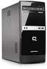
1 Product Description Chassis Designations The following subsection illustrates the 500B and 505B chassis design. Microtower (MT) Chassis Designations 1 - Compaq 500B | Maintenance & Service Guide: Compaq 500B and 505B Minitower Bu - Page 10
x1, one PCI expansion slot ● 300W passive Power Factor Correction (PFC) and non-PFC power supply ● Six USB 2.0 ports ● Realtek 10/100 Mbps Ethernet controller ● Integrated 5.1 channel audio ● Support for HP Kensington MicroSaver cable lock ● Windows 7 logo compliance 2 Chapter 1 Product Description - Compaq 500B | Maintenance & Service Guide: Compaq 500B and 505B Minitower Bu - Page 11
systems the cooling fan is on even when the computer is in the "Standby," or "Suspend" modes. The power cord should always be disconnected before servicing a unit. 5. Disconnect the power cord from the electrical outlet and then from the computer. 6. Disconnect all peripheral device cables from the - Compaq 500B | Maintenance & Service Guide: Compaq 500B and 505B Minitower Bu - Page 12
computer. Slide the cover about 2.4 cm (1 inch) to remove it. NOTE: You may want to lay the computer on its side to install internal parts. Be sure the side with the access panel is facing up. Figure 2-2 Removing the Computer Access Panel 4 Chapter 2 Removal and Replacement Procedures Microtower (MT - Compaq 500B | Maintenance & Service Guide: Compaq 500B and 505B Minitower Bu - Page 13
4. Remove the side panel by lifting it away from the computer. Figure 2-3 Removing the Computer Access Panel To replace the access panel, reverse the removal steps. Access Panel 5 - Compaq 500B | Maintenance & Service Guide: Compaq 500B and 505B Minitower Bu - Page 14
Disassembly on page 3). 2. Remove the access panel (Access Panel on page 4). 3. Pull each of the three side tabs that secure the front bezel to the computer, to release the front bezel. Figure 2-4 Removing the Front Bezel 6 Chapter 2 Removal and Replacement Procedures Microtower (MT) Chassis - Compaq 500B | Maintenance & Service Guide: Compaq 500B and 505B Minitower Bu - Page 15
4. Swing the front bezel out to remove from the computer. Figure 2-5 Removing the Front Bezel NOTE: The appearance of the front bezel may vary. To reinstall the front bezel, reverse the removal procedure. Front Bezel 7 - Compaq 500B | Maintenance & Service Guide: Compaq 500B and 505B Minitower Bu - Page 16
-ECC memory technologies ● single-sided and double-sided DIMMs ● DIMMs constructed with x8 and x16 DDR devices; DIMMs constructed with x4 SDRAM are not supported NOTE: The system will not operate properly if you install unsupported DIMMs. 8 Chapter 2 Removal and Replacement Procedures Microtower (MT - Compaq 500B | Maintenance & Service Guide: Compaq 500B and 505B Minitower Bu - Page 17
Populating DIMM Sockets There are two DIMM sockets on the system board. Figure 2-6 DIMM Socket Locations - 500B Figure 2-7 DIMM Socket Locations - 505B Table 2-1 DIMM Socket Locations Item Description 1 DIMM1 socket, Channel A (populate first) 2 DIMM2 socket, Channel A NOTE: A DIMM must - Compaq 500B | Maintenance & Service Guide: Compaq 500B and 505B Minitower Bu - Page 18
the memory module sockets on the system board (500B shown). WARNING! To reduce risk of personal injury from hot surfaces, allow the internal system components to cool before touching. Figure 2-8 DIMM locations (500B shown) 10 Chapter 2 Removal and Replacement Procedures Microtower (MT) Chassis - Compaq 500B | Maintenance & Service Guide: Compaq 500B and 505B Minitower Bu - Page 19
to install any additional modules. 7. Replace the computer access panel. 8. Reconnect the power cord and any external devices, then turn on the computer. The computer should automatically recognize the additional memory when you turn on the computer. 9. Lock any security devices that were disengaged - Compaq 500B | Maintenance & Service Guide: Compaq 500B and 505B Minitower Bu - Page 20
- 500B Figure 2-11 Expansion Slot Locations - 505B Table 2-2 Expansion Slot Locations Item Description 1 PCI Express x16 expansion slot 2 PCI Express x1 expansion slot 3 PCI Express x1 expansion slot 4 PCI expansion slot 12 Chapter 2 Removal and Replacement Procedures Microtower (MT - Compaq 500B | Maintenance & Service Guide: Compaq 500B and 505B Minitower Bu - Page 21
x1, x4, x8, or x16 expansion card in the PCI Express x16 expansion slot. To remove, replace, or add an expansion card: 1. Prepare the computer for disassembly (Preparation for Disassembly on page 3). 2. Remove the access panel (Access Panel on page 4). 3. Locate the add-in cards at the back of - Compaq 500B | Maintenance & Service Guide: Compaq 500B and 505B Minitower Bu - Page 22
5. Remove the bracket cover. Figure 2-14 Removing the bracket cover 6. If you are removing a graphics card, press on the latch to release it. Figure 2-15 Press the latch to release the graphics card 14 Chapter 2 Removal and Replacement Procedures Microtower (MT) Chassis - Compaq 500B | Maintenance & Service Guide: Compaq 500B and 505B Minitower Bu - Page 23
7. Remove the graphics card from the card slot. NOTE: If you are removing a PCI Express x16 free from the socket. Be sure not to scrape the card against the other components. Figure 2-16 Removing the graphics card from the slot 8. For other add-in cards, move the card back and forth gently to free it - Compaq 500B | Maintenance & Service Guide: Compaq 500B and 505B Minitower Bu - Page 24
9. Lift the card out of the computer. Figure 2-18 Lifting the card from the computer 10. If present, remove any cables connected to the add-in card. Figure 2-19 cover for proper cooling of internal components during operation. 16 Chapter 2 Removal and Replacement Procedures Microtower (MT) Chassis - Compaq 500B | Maintenance & Service Guide: Compaq 500B and 505B Minitower Bu - Page 25
an expansion card, press firmly on the card so that the whole connector seats properly in the expansion card slot. 14. If you are replacing a graphics card, verify that the latch in the computer snaps back into place. Figure 2-21 Replacing - Compaq 500B | Maintenance & Service Guide: Compaq 500B and 505B Minitower Bu - Page 26
15. Press straight down until the card is fully seated in the card slot. Figure 2-22 Seating the card 16. Replace the bracket cover on the back of the computer. Figure 2-23 Replacing the bracket cover 18 Chapter 2 Removal and Replacement Procedures Microtower (MT) Chassis - Compaq 500B | Maintenance & Service Guide: Compaq 500B and 505B Minitower Bu - Page 27
Setup (F10) Utility Guide for instructions on using Computer Setup. Cable Management Always follow good cable management practices when working inside the computer. ● Keep cables away from major heat sources like the heatsink. ● Do not jam cables on top of expansion cards or memory modules. Printed - Compaq 500B | Maintenance & Service Guide: Compaq 500B and 505B Minitower Bu - Page 28
supply, 24-pin power supply, 4-pin chassis fan heat sink fan front power button/LED front I/O USB cable front I/O audio hard drive optical drive PCI expansion slot PCIe x1 expansion slot PCIe x1 expansion slot PCIe x16 expansion slot 20 Chapter 2 Removal and Replacement Procedures Microtower (MT - Compaq 500B | Maintenance & Service Guide: Compaq 500B and 505B Minitower Bu - Page 29
computer supports one optical drive and one hard drive. This section describes the procedure for replacing or upgrading the drives. A Torx T-15 screwdriver is needed to remove and install the guide computer, and unplug the power cord. Do not remove a drive while the computer , or products that have - Compaq 500B | Maintenance & Service Guide: Compaq 500B and 505B Minitower Bu - Page 30
Connections - 500B Figure 2-26 System Board Drive Connections - 505B Table 2-5 System Board Drive Connections No. System Board Label - 500B 1 SATA1 2 SATA2 System Board Label - 505B SATA0 SATA1 Color dark blue white 22 Chapter 2 Removal and Replacement Procedures Microtower (MT) Chassis - Compaq 500B | Maintenance & Service Guide: Compaq 500B and 505B Minitower Bu - Page 31
front bezel (Front Bezel on page 6). 4. Disconnect the power cable (1) and data cable (2) from the rear of the optical drive. Figure 2-27 Disconnecting the power and data cables 5. Remove the screws that fasten the disc drive in the computer. Figure 2-28 Removing the optical drive screws Drives 23 - Compaq 500B | Maintenance & Service Guide: Compaq 500B and 505B Minitower Bu - Page 32
the drive slightly forward. Figure 2-29 Push the drive forward 7. Pull the disc drive out through the front of the computer. Figure 2-30 Pull the drive from the computer NOTE: To install an optical drive, refer to Replacing an Optical Driveon page 25. 24 Chapter 2 Removal and Replacement Procedures - Compaq 500B | Maintenance & Service Guide: Compaq 500B and 505B Minitower Bu - Page 33
, remove the screws before inserting the drive into the chassis. 5. Push the replacement disc drive partially into the drive bay in the computer. Figure 2-31 Installing the optical drive 6. Connect the power cable (1) and data cable (2) to the rear of the optical drive. Figure 2-32 Connecting the - Compaq 500B | Maintenance & Service Guide: Compaq 500B and 505B Minitower Bu - Page 34
Disc Set to restore the operating system, software drivers, and any software applications that were preinstalled on the computer. If you do not have this CD set, select Start > HP Backup and Recovery and create it now. 1. Prepare the computer for disassembly (Preparation for Disassembly on page - Compaq 500B | Maintenance & Service Guide: Compaq 500B and 505B Minitower Bu - Page 35
4. Locate the external drive bay at the front of the computer, below the optical drive bays. Figure 2-35 Locating the hard drive 5. Disconnect the power (1) and data (2) cables by squeezing the latch on the connector and pulling to remove. Figure 2-36 Disconnecting the hard drive cables Drives 27 - Compaq 500B | Maintenance & Service Guide: Compaq 500B and 505B Minitower Bu - Page 36
computer. Figure 2-37 Removing the hard drive screws 7. Pull the hard drive out of the front of the computer. Figure 2-38 Pulling the hard drive from the computer NOTE: To install a hard drive, refer to Replacing a Hard Driveon page 29. 28 Chapter 2 Removal and Replacement Procedures Microtower (MT - Compaq 500B | Maintenance & Service Guide: Compaq 500B and 505B Minitower Bu - Page 37
Replacing a Hard Drive 1. Follow the steps in Removing a Hard Drive on page 26 to remove the hard drive. 2. Slide the replacement hard disk drive into the bay. NOTE: If you are replacing an old drive with a new drive, use the four retainer screws from the old drive to - Compaq 500B | Maintenance & Service Guide: Compaq 500B and 505B Minitower Bu - Page 38
the two screws to secure the hard disk drive to the bay. Figure 2-41 Replacing the screws that secure the hard drive 5. Attach the power and data connectors to the back of the drive. Figure 2-42 Attaching the connectors 6. Replace the front bezel, computer access panel, and all cables. 7. Lock any - Compaq 500B | Maintenance & Service Guide: Compaq 500B and 505B Minitower Bu - Page 39
2. Remove the access panel (Access Panel on page 4) 3. Lay the computer on its side with the front facing toward you. 4. Remove the front the housing up (2), and then pull the assembly away from the chassis while guiding the cables through the hole in the chassis. Figure 2-43 Removing the front - Compaq 500B | Maintenance & Service Guide: Compaq 500B and 505B Minitower Bu - Page 40
switch upward (2), and then pull it away from the chassis while guiding the wires through the hole in the chassis. Figure 2-44 Removing the power switch To install the power switch/LED assembly, reverse the removal procedures. 32 Chapter 2 Removal and Replacement Procedures Microtower (MT) Chassis - Compaq 500B | Maintenance & Service Guide: Compaq 500B and 505B Minitower Bu - Page 41
for disassembly (Preparation for Disassembly on page 3). 2. Remove the access panel (Access Panel on page 4). 3. Lay the computer on its side with the rear facing toward you. 4. Disconnect the cable that connects the system fan to the system board. 5. Remove the four Phillips - Compaq 500B | Maintenance & Service Guide: Compaq 500B and 505B Minitower Bu - Page 42
500B 1. Prepare the computer for disassembly (Preparation for Disassembly on page 3). 2. Remove the access panel (Access Panel on page 4). 3. Lay the computer on its side with the rear facing toward you. 4. Disconnect the heat sink fan control and Replacement Procedures Microtower (MT) Chassis - Compaq 500B | Maintenance & Service Guide: Compaq 500B and 505B Minitower Bu - Page 43
(Preparation for Disassembly on page 3). 2. Remove the access panel (Access Panel on page 4). 3. Lay the computer on its side with the rear facing toward you. 4. Disconnect the heat sink fan control cable from the system board. 5. Lift the lever (1) that secures the heat sink latch to the heat sink - Compaq 500B | Maintenance & Service Guide: Compaq 500B and 505B Minitower Bu - Page 44
4). 3. Lay the computer on its side with the rear facing toward you. 4. Disconnect the heatsink control cable from the system board and remove the heatsink Heat sink assembly (Intel) - Model 500B on page 34). 5. the spares kit. 36 Chapter 2 Removal and Replacement Procedures Microtower (MT) Chassis - Compaq 500B | Maintenance & Service Guide: Compaq 500B and 505B Minitower Bu - Page 45
screws and attach the heat sink control cable to the system board. CAUTION update the system ROM to ensure that the latest version of the BIOS is being used on the computer. The latest system ROM BIOS can be found on the Web at: http:\\h18000.www1.hp.com/support/files. Processor (Intel) - Model 500B - Compaq 500B | Maintenance & Service Guide: Compaq 500B and 505B Minitower Bu - Page 46
Model 505B 1. Prepare the computer for disassembly (Preparation for Disassembly on page 3). 2. Remove the access panel (Access Panel on page 4). 3. Disconnect the heatsink control cable from the system board and the processor. 38 Chapter 2 Removal and Replacement Procedures Microtower (MT) Chassis - Compaq 500B | Maintenance & Service Guide: Compaq 500B and 505B Minitower Bu - Page 47
four captive screws and attach the heat sink control cable to the system board. CAUTION: heat update the system ROM to ensure that the latest version of the BIOS is being used on the computer. The latest system BIOS can be found on the Web at: http://h18000.www1.hp.com/support/files. Power Supply - Compaq 500B | Maintenance & Service Guide: Compaq 500B and 505B Minitower Bu - Page 48
vary from the ones shown below. 7. Trace the power supply cables to the system components: ● Optical disc drives (A) ● Hard disk drives (B) ● Motherboard main power (C) ● Motherboard fan (D) Figure 2-51 Power supply connections 40 Chapter 2 Removal and Replacement Procedures Microtower (MT) Chassis - Compaq 500B | Maintenance & Service Guide: Compaq 500B and 505B Minitower Bu - Page 49
8. Disconnect the power cable from the optical disc and hard disk drives by squeezing the latch (1) on the connectors and pulling to remove. Figure 2-52 Disconnecting the power cable Power Supply 41 - Compaq 500B | Maintenance & Service Guide: Compaq 500B and 505B Minitower Bu - Page 50
must be pressed to detach the connector from the motherboard. Figure 2-53 Disconnecting the main system board power connector Some connectors may have latches that must be pressed to remove them. Figure 2-54 Connector Latches 42 Chapter 2 Removal and Replacement Procedures Microtower (MT) Chassis - Compaq 500B | Maintenance & Service Guide: Compaq 500B and 505B Minitower Bu - Page 51
all other power connectors from the motherboard. Figure 2-55 Disconnecting power connectors 11. Remove the four screws that connect the power supply to the computer. The images below illustrate possible power supply screw locations. Figure 2-56 Removing the power supply screws Power Supply 43 - Compaq 500B | Maintenance & Service Guide: Compaq 500B and 505B Minitower Bu - Page 52
computer. Figure 2-58 Removing the power supply from the computer To install the power supply, reverse the removal procedure. Note that there is a latch, a guide, and a ledge on the computer that help secure the power supply. 44 Chapter 2 Removal and Replacement Procedures Microtower (MT) Chassis - Compaq 500B | Maintenance & Service Guide: Compaq 500B and 505B Minitower Bu - Page 53
Figure 2-59 Power supply securing features System Board When replacing the system board, be sure that the following components are removed from the defective system board and installed on the replacement system board: ● Memory modules ● Processor ● Expansion modules To remove the system board: 1. - Compaq 500B | Maintenance & Service Guide: Compaq 500B and 505B Minitower Bu - Page 54
a new system board, always update the system ROM to ensure that the latest version of the BIOS is being used on the computer. The latest system ROM BIOS can be found at: http: \\h18000.www1.hp.com/support/files. Battery The battery that comes with your computer provides power to the real-time clock - Compaq 500B | Maintenance & Service Guide: Compaq 500B and 505B Minitower Bu - Page 55
battery only with the HP/Compaq spare designated for this product. CAUTION: Before replacing the battery, it is important to back up the computer CMOS settings. When the battery is removed or replaced, the CMOS settings will be cleared. Refer to the Troubleshooting Guide for information on backing - Compaq 500B | Maintenance & Service Guide: Compaq 500B and 505B Minitower Bu - Page 56
of the battery. 3. Replace the computer access panel. 4. Plug in the computer and turn on power to the computer. 5. Reset the date and time, your passwords, and any special system setups, using Computer Setup. Refer to the Computer Setup (F10) Utility Guide. Type 3 Battery Holder 1. Pull back on - Compaq 500B | Maintenance & Service Guide: Compaq 500B and 505B Minitower Bu - Page 57
battery and position the clip back in place. 3. Replace the computer access panel. 4. Plug in the computer and turn on power to the computer. 5. Reset the date and time, your passwords, and any special system setups, using Computer Setup. Refer to the Computer Setup (F10) Utility Guide. Battery 49 - Compaq 500B | Maintenance & Service Guide: Compaq 500B and 505B Minitower Bu - Page 58
(F10) Setup Model 500B - Computer Setup (F10) Utilities Use Computer Setup (F10) Utility to do the following: ● Change factory default settings. ● Set the system date and time. ● Set, view, change, or verify the system configuration, including settings for graphics, audio, storage, communications - Compaq 500B | Maintenance & Service Guide: Compaq 500B and 505B Minitower Bu - Page 59
CAUTION: Do NOT turn the computer power OFF while the ROM is saving the Computer Setup (F10) changes because the CMOS could become corrupted. It is safe to turn off the computer only after exiting the F10 Setup screen. Computer Setup-Main NOTE: Support for specific Computer Setup options may vary - Compaq 500B | Maintenance & Service Guide: Compaq 500B and 505B Minitower Bu - Page 60
Self-Test System Information (view only) ● Installed Memory ● Memory Bank 1 ● Memory Bank 2 ● BIOS Revision ● Core Version ● Model Number ● Serial Number ● Product Number ● Asset Tag Computer Setup-Advanced NOTE: Support for specific Computer Setup options may vary depending on the - Compaq 500B | Maintenance & Service Guide: Compaq 500B and 505B Minitower Bu - Page 61
Allows you to change the supervisor password. Onboard Audio Allows you to set the onboard audio to: ● Auto ● Disabled ● Enabled Microphone Input Allows you to set disable/enable microphone input. Computer Setup-Power NOTE: Support for specific Computer Setup options may vary depending on - Compaq 500B | Maintenance & Service Guide: Compaq 500B and 505B Minitower Bu - Page 62
Recovery Enables/disables the ability to press the F11 key to access the recovery ● CD-ROM Group ● Hard Drive Group ● Floppy Group Network Boot Group Network Group Boot Priority Specifies boot device priority within bootable network devices. Computer Setup-Exit NOTE: Support for specific Computer - Compaq 500B | Maintenance & Service Guide: Compaq 500B and 505B Minitower Bu - Page 63
Computer Setup (F10) Utility to do the following: ● Change factory default settings. ● Set the system date and time. ● Set, view, change, or verify the system configuration, including settings for graphics, audio, storage, communications, and input devices. ● View settings for processor and memory - Compaq 500B | Maintenance & Service Guide: Compaq 500B and 505B Minitower Bu - Page 64
CAUTION: Do NOT turn the computer power OFF while the ROM is saving the Computer Setup (F10) changes because the CMOS could become corrupted. It is safe to turn off the computer only after exiting the F10 Setup screen. Computer Setup-Main NOTE: Support for specific Computer Setup options may vary - Compaq 500B | Maintenance & Service Guide: Compaq 500B and 505B Minitower Bu - Page 65
-Test System Information (view only) ● Installed Memory ● Memory Bank 1 ● Memory Bank 2 ● BIOS Revision ● Core Version ● Model Number ● Product Number ● Asset Tag (press Enter to change) Computer Setup-Advanced NOTE: Support for specific Computer Setup options may vary depending on the - Compaq 500B | Maintenance & Service Guide: Compaq 500B and 505B Minitower Bu - Page 66
each port. Change Supervisor Password Allows you to change supervisor password. Computer Setup-Power NOTE: Support for specific Computer Setup options may vary depending on the hardware configuration. Table A-8 Computer Setup-Power Option Description After AC Power Failure Allows you to - Compaq 500B | Maintenance & Service Guide: Compaq 500B and 505B Minitower Bu - Page 67
device priority within CD/DVD drives. Priority Hard Drive Group Boot Specifies boot device priority within hard drives. Priority Network Group Boot Priority Specifies boot device priority within bootable network devices. Computer Setup-Exit NOTE: Support for specific Computer Setup options may - Compaq 500B | Maintenance & Service Guide: Compaq 500B and 505B Minitower Bu - Page 68
Table A-10 Computer Setup-Exit Option Description Exit Saving Changes Press Enter to exit saving changes. Exit Discarding Changes Press Enter to load setup defaults. Discard Changes Press Enter to discard changes. Save Changes Press Enter to save changes. 60 Appendix A Computer (F10) Setup - Compaq 500B | Maintenance & Service Guide: Compaq 500B and 505B Minitower Bu - Page 69
pause 1. Check the type of drive you are using and use the correct media type. 2. Replace the diskette or CD with a new one. 3 short beeps, 3 Flashing not ready (missing utility or Upgrade the BIOS to proper version. second pause BIOS image file, etc.) Interpreting Diagnostic Beep Codes 61 - Compaq 500B | Maintenance & Service Guide: Compaq 500B and 505B Minitower Bu - Page 70
. 5 short beeps, 3 BIOS recovery was successful second pause No action required. LED Codes The following table describes the LED states for the Compaq 500B and 505B MT Desktop PCs. LED Power LED Indicator Drive LED Indicator State System on (normal operation) Suspend to RAM Computer off Normal - Compaq 500B | Maintenance & Service Guide: Compaq 500B and 505B Minitower Bu - Page 71
drive, memory, and CPU. The diagnostic tool can check DIMMs to find out whether they are improperly configured, incorrectly installed, or defective. To access HP Diagnostic Tools, the user presses the F9 button when booting the PC. If HP Diagnostic Tools or POST beep codes indicate a memory error - Compaq 500B | Maintenance & Service Guide: Compaq 500B and 505B Minitower Bu - Page 72
or a DIMM socket is bad or unusable. Open the computer casing and reseat the DIMM. If this does not work, try BIOS will handle them as follows: For SKUs including an OS=MSV or an OS=LX in the SMBIOS Type 11 data, 1. Handle the first serious error, SMART error, as follows: Display "xxx: Hard disk - Compaq 500B | Maintenance & Service Guide: Compaq 500B and 505B Minitower Bu - Page 73
button LED is dual-color capable, check the SMBIOS Type 11 data structure. If the SMBIOS Type 11 data structure contains the string DLED (NOT case-sensitive), the system supports the dual-color power button LED and therefore, the BIOS support as described above is required. Using the Setup Utility - Compaq 500B | Maintenance & Service Guide: Compaq 500B and 505B Minitower Bu - Page 74
BIOS Updates HP periodically releases system BIOS updates, which are available from the HP website. These updates often contain fixes for known issues in the BIOS. To find out whether a PC needs a BIOS update, compare the current BIOS version number against the latest version available for download. - Compaq 500B | Maintenance & Service Guide: Compaq 500B and 505B Minitower Bu - Page 75
the cap on pins 1-2 for 5 to 10 seconds. 7. Replace the jumper on pins 2-3. 8. Reinstall the battery. 9. Replace the access panel, external equipment, and reconnect the power cord. 10. Turn on the computer. 11. Hold down the F1 key during boot and enter BIOS setup to re-enter data. Clearing CMOS 67 - Compaq 500B | Maintenance & Service Guide: Compaq 500B and 505B Minitower Bu - Page 76
, optical drive, graphics, audio, memory, and software problems. If you encounter problems with the computer, refer to the tables in this chapter for probable causes and recommended solutions. NOTE: For information on specific error messages that may appear on the screen during Power-On Self-Test - Compaq 500B | Maintenance & Service Guide: Compaq 500B and 505B Minitower Bu - Page 77
call is handled properly: ● Be in front of your computer when you call. ● Write down the computer serial number, product ID number, and monitor serial number before calling. ● Spend time troubleshooting the problem with the service technician. ● Remove any hardware that was recently added to your - Compaq 500B | Maintenance & Service Guide: Compaq 500B and 505B Minitower Bu - Page 78
that it is supported on the system computer to a live AC outlet prolongs the life of the RTC battery. First, reset the date and time under Control Panel (Computer Setup can also be used to update the RTC date and time). If the problem persists, replace the RTC battery. 70 Appendix C Troubleshooting - Compaq 500B | Maintenance & Service Guide: Compaq 500B and 505B Minitower Bu - Page 79
POST Error/Warning Messages on page 64 to interpret is beeping a code. the error code. Solving Power Problems Common causes and solutions for power problems are listed in the following table. Table C-2 Solving Power Problems The computer will not turn on. Cause Solution Cables to the external - Compaq 500B | Maintenance & Service Guide: Compaq 500B and 505B Minitower Bu - Page 80
. The drive's SATA controller is disabled in HP Setup. Reconnect the power cable and ensure that all four pins are connected. Drive responds slowly after initial power up. Run Computer Setup and increase the POST Delay in Advanced > Power-On Options. Nonsystem disk/NTLDR missing message. Cause - Compaq 500B | Maintenance & Service Guide: Compaq 500B and 505B Minitower Bu - Page 81
check for new releases of this software on the HP Software Download Web page. Table C-4 Solving Media Card Reader Problems The memory card reader does not appear in My Computer or Windows Explorer. Cause Solution You are using an adapter for a type of memory card not supported by the reader - Compaq 500B | Maintenance & Service Guide: Compaq 500B and 505B Minitower Bu - Page 82
. Disconnect the computer from power and straighten the bent pins with the end of a mechanical pencil. If a pin has bent to the point where it is touching another pin, replace the memory card reader or have the computer serviced. Solving Display Problems If you encounter display problems, see the - Compaq 500B | Maintenance & Service Guide: Compaq 500B and 505B Minitower Bu - Page 83
contrast settings. Solving Audio Problems If the computer has audio features and you encounter audio problems, see the common Problems Keyboard commands and typing are not recognized by the computer. Cause Solution Keyboard connector is not properly connected. Replace the keyboard. Computer - Compaq 500B | Maintenance & Service Guide: Compaq 500B and 505B Minitower Bu - Page 84
debugging the network cabling. Table C-9 Solving Network Problems Network driver does not detect network controller. Cause Solution Network controller is disabled. Incorrect network driver. Run the HP Setup Utility and enable the network controller. Check the network controller documentation for - Compaq 500B | Maintenance & Service Guide: Compaq 500B and 505B Minitower Bu - Page 85
configured properly. Verify that the computer is properly connected to the network, that a DHCP Server is present, and that the Remote System Installation Server contains drivers for the network controller. Solving Memory Problems If you encounter memory problems, some common causes and solutions - Compaq 500B | Maintenance & Service Guide: Compaq 500B and 505B Minitower Bu - Page 86
Drive is not connected properly or not properly configured. Solution 1. Power off the PC. 2. Reconnect the power and data cables to the drive. 3. Reboot the PC 4. Reinstall the correct (new or updated) device driver. An optical drive cannot read a CD or DVD disc. Cause The disc is upside down or - Compaq 500B | Maintenance & Service Guide: Compaq 500B and 505B Minitower Bu - Page 87
and solutions listed in the following table. Table C-12 Solving Front Panel Component Problems A USB device is not recognized by the computer. Cause Solution The device does not have power. If the USB device requires AC power, be sure one end is connected to the device and one end is connected - Compaq 500B | Maintenance & Service Guide: Compaq 500B and 505B Minitower Bu - Page 88
appendix contains the pin assignments for many computer and workstation connectors. Some of these connectors may not be used on the product being serviced. 4-Pin Power (for CPU) Connector and Icon Pin Signal 1 GND 2 GND 3 +12V CPU 4 -12V CPU Ethernet BNC Connector and Icon Pin Signal - Compaq 500B | Maintenance & Service Guide: Compaq 500B and 505B Minitower Bu - Page 89
Microphone Connector and Icon (1/8" miniphone) 1 23 Headphone Connector and Icon (1/8" miniphone) 1 23 Line-in Audio Connector and Icon (1/8" miniphone) 1 23 Line-out Audio Connector and Icon (1/8" miniphone) 1 23 Pin 1 (Tip) 2 (Ring) 3 (Shield) Signal Audio_left Audio_Right Ground Pin 1 (Tip) 2 - Compaq 500B | Maintenance & Service Guide: Compaq 500B and 505B Minitower Bu - Page 90
Signal 9 +5V (fused) 10 Ground 11 Not used 12 DDC Serial Data 13 Horizontal Sync 14 Vertical Sync 15 DDC Serial Clock 24-Pin Power Connector 24 12 Pin Signal 1 +3.3V 2 +3.3V 3 GND 4 +5V 5 GND 6 +5V 13 1 Pin Signal 7 GND 8 POK 9 +5 Vaux 10 +12V 11 +12V 12 +3.3V - Compaq 500B | Maintenance & Service Guide: Compaq 500B and 505B Minitower Bu - Page 91
PCI Express x1, x4, x8, and x16 PCI Express Connector Pin A Pin Signal Pin Signal 1 PRSNT1 6 JTAG3 2 +12V 7 JTAG4 3 +12V 8 JTAG5 4 GND 9 +3.3V 5 JTAG2 10 +3.3V 26 PERn(2) 31 GND 27 GND 32 RSVD 28 GND 33 RSVD 29 PERp3 34 GND 30 PERn3 35 PERp4 51 GND 56 PERp9 52 PERp8 57 - Compaq 500B | Maintenance & Service Guide: Compaq 500B and 505B Minitower Bu - Page 92
PCI Express x1, x4, x8, and x16 PCI Express Connector Pin B Pin Signal Pin Signal 1 +12V 6 SMDAT 2 +12V 7 GND 3 RSVD 8 +3.3 V 4 GND 9 JTAG1 5 SMCLK 10 3.3vAux 26 GND 31 PRSNT2# 27 PETp3 32 GND 28 PETn3 33 PETp4 29 GND 34 PETn4 30 RSVD 35 GND 51 PETn8 56 GND 52 GND 57 GND - Compaq 500B | Maintenance & Service Guide: Compaq 500B and 505B Minitower Bu - Page 93
described in this chapter is essential for proper service. CAUTION: When the computer is plugged into an AC power source, voltage is always applied to the system board. You must disconnect the power cord from the power source before opening the computer to prevent system board or component damage - Compaq 500B | Maintenance & Service Guide: Compaq 500B and 505B Minitower Bu - Page 94
V 26,500 V 21,000 V NOTE: 700 volts can degrade a product. Preventing Electrostatic Damage to Equipment Many electronic components are sensitive to ESD. can be used at standing workstations and are compatible with most types of shoes or boots. On conductive floors or dissipative floor mats - Compaq 500B | Maintenance & Service Guide: Compaq 500B and 505B Minitower Bu - Page 95
parts, and assemblies by the case or PCB laminate. Handle them only at static-free work areas. ● Turn off power and input signals before inserting and -dissipative table or floor mats with hard tie to ground ● Field service kits ● Static awareness labels ● Wrist straps and footwear straps providing - Compaq 500B | Maintenance & Service Guide: Compaq 500B and 505B Minitower Bu - Page 96
against the front of the desktop unit as this also restricts airflow. ● Occasionally clean the air vents on all vented sides of the computer. Lint, dust, and the computer and keyboard. ● Never cover the ventilation slots on the monitor with any type of material. ● Install or enable power management - Compaq 500B | Maintenance & Service Guide: Compaq 500B and 505B Minitower Bu - Page 97
. To clean the tops of the keys or the keyboard body, follow the procedures described in Cleaning the Computer Case on page 89. When cleaning debris from under the keys, review all rules in General Cleaning Safety Precautions on page 89 before following these procedures: CAUTION: Use safety glasses - Compaq 500B | Maintenance & Service Guide: Compaq 500B and 505B Minitower Bu - Page 98
mouse body, follow the procedures in Cleaning the Computer Case on page 89. Service Considerations Listed below are some of the considerations that you should keep in mind during the disassembly and assembly of the computer. Power Supply Fan The power supply fan is a variable-speed fan based on the - Compaq 500B | Maintenance & Service Guide: Compaq 500B and 505B Minitower Bu - Page 99
cases, avoid bending or twisting the cables, and ensure that the cables are routed in such a way that they cannot be caught or snagged by parts being removed or replaced. CAUTION: When servicing this computer products that have magnetic fields such as monitors or speakers. Service Considerations 91 - Compaq 500B | Maintenance & Service Guide: Compaq 500B and 505B Minitower Bu - Page 100
computer provides power to the real-time clock and has a minimum lifetime of about three years. See the appropriate removal and replacement chapter for the chassis you are working on in this guide for instructions return them to HP, their authorized partners, or their agents. 92 Appendix - Compaq 500B | Maintenance & Service Guide: Compaq 500B and 505B Minitower Bu - Page 101
Drive Guidelines and Features NOTE: HP only supports the use of SATA hard drives on these models of computer. No Parallel ATA (PATA) drives are supported. SATA Hard Drives Serial ATA Hard Drive Characteristics Number of pins/conductors in data cable Number of pins in power cable Maximum data cable - Compaq 500B | Maintenance & Service Guide: Compaq 500B and 505B Minitower Bu - Page 102
SMART ATA Drives The Self Monitoring Analysis and Recording Technology (SMART) ATA drives for the HP Personal Computers have built-in drive failure prediction that warns the user or network administrator of an impending failure or crash of the hard drive. The SMART drive tracks fault prediction and - Compaq 500B | Maintenance & Service Guide: Compaq 500B and 505B Minitower Bu - Page 103
G Power Cord Set Requirements The power supplies on some computers have external power switches. The voltage select switch feature on the computer permits it to operate from any line voltage between 100-120 or 220-240 volts AC. Power supplies on those computers that do not have external power - Compaq 500B | Maintenance & Service Guide: Compaq 500B and 505B Minitower Bu - Page 104
Requirements Additional requirements specific to a country are shown in parentheses and explained below. Country (2) UL Germany (1) VDE 1. The flexible cord must be Type HO5VV-F, 3-conductor, 0.75mm2 conductor size. Power cord set fittings (appliance coupler and wall plug) must bear - Compaq 500B | Maintenance & Service Guide: Compaq 500B and 505B Minitower Bu - Page 105
no direct sustained sunlight. Maximum rate of change is 10° C/Hr. The upper limit may be limited by the type and number of options installed. Shock The level of shock the product can withstand with no damage being incurred is 35 G peak input acceleration during an 11-millisecond trapezoidal shock - Compaq 500B | Maintenance & Service Guide: Compaq 500B and 505B Minitower Bu - Page 106
average LpAm 32 dBA = 44 dBA NOTE: Listed are the declared A-weighted sound power levels (LWAd) and declared average desktop seated operator position A-weighted sound pressure levels (LpAm) when the product is operating in a 23°C (73.4°F) ambient environment. NOTE: Noise emissions were measured - Compaq 500B | Maintenance & Service Guide: Compaq 500B and 505B Minitower Bu - Page 107
46 beep codes 61 BIOS DIMM test 63 BIOS updates 66 C cable connections 20 cable management 19 cable pinouts SATA data 93 cautions AC power 85 cables 91 cooling fan 90 electrostatic discharge 85 keyboard cleaning 89 keyboard keys 90 CD-ROM or DVD problems 78 chassis, illustrated 1 cleaning computer - Compaq 500B | Maintenance & Service Guide: Compaq 500B and 505B Minitower Bu - Page 108
specific 96 power problems 71 power supply fan 90 removal and replacement 39 power switch/LED removal and replacement 32 preparation for disassembly 3 problems audio 75 CD-ROM or DVD 78 front panel 79 general 70 hard drive 72 keyboard 75 Media Card Reader 73 memory 77 monitor 74 mouse 75 network
-
 1
1 -
 2
2 -
 3
3 -
 4
4 -
 5
5 -
 6
6 -
 7
7 -
8
-
9
-
10
-
11
-
12
-
13
-
14
-
15
-
16
-
17
-
18
-
19
-
20
-
21
-
22
-
23
-
24
-
25
-
26
-
27
-
28
-
29
-
30
-
31
-
32
-
33
-
34
-
35
-
36
-
37
-
38
-
39
-
40
-
41
-
42
-
43
-
44
-
45
-
46
-
47
-
48
-
49
-
50
-
51
-
52
-
53
-
54
-
55
-
56
-
57
-
58
-
59
-
60
-
61
-
62
-
63
-
64
-
65
-
66
-
67
-
68
-
69
-
70
-
71
-
72
-
73
-
74
-
75
-
76
-
77
-
78
-
79
-
80
-
81
-
82
-
83
-
84
-
85
-
86
-
87
-
88
-
89
-
90
-
91
-
92
-
93
-
94
-
95
-
96
-
97
-
98
-
99
-
100
-
101
-
102
-
103
-
104
-
105
-
106
-
107
-
108
 |
 |

Maintenance & Service Guide
Compaq 500B and 505B Minitower Business PC