Compaq 500B Maintenance & Service Guide: Compaq 500B and 505B Minitower Bu - Page 28
Cable Connections
 |
View all Compaq 500B manuals
Add to My Manuals
Save this manual to your list of manuals |
Page 28 highlights
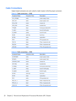
Cable Connections System board connectors are color-coded to make it easier to find the proper connection. Table 2-3 Cable connections - 500B Connector Name Connector Color Description ATX_POWER white power supply, 24-pin ATX_12V white power supply, 4-pin SYS_FAN1 brown chassis fan CPU_FAN white heat sink fan F PANEL black front power button/LED F_USB1 white front I/O USB cable F_AUDIO yellow front I/O audio SATA1 dark blue hard drive SATA2 white optical drive PCI2 white PCI expansion slot PCIE1X black PCIe x1 expansion slot PCIE1X1 black PCIe x1 expansion slot PCIE16X black PCIe x16 expansion slot Table 2-4 Cable connections - 505B Connector Name Connector Color ATXPOWER white ATXCPU white CHASSIS_FAN1 brown CPU FAN white F_PANEL black F_USB2 white F_AUDIO yellow SATA0 dark blue SATA1 white PCI1 white PCIE_X1_1 black PCIE_X1_2 black PCIE X16 black Description power supply, 24-pin power supply, 4-pin chassis fan heat sink fan front power button/LED front I/O USB cable front I/O audio hard drive optical drive PCI expansion slot PCIe x1 expansion slot PCIe x1 expansion slot PCIe x16 expansion slot 20 Chapter 2 Removal and Replacement Procedures Microtower (MT) Chassis
-
 1
1 -
2
-
3
-
4
-
5
-
6
-
7
-
8
-
9
-
10
-
11
-
12
-
13
-
14
-
15
-
16
-
17
-
18
-
19
-
20
-
21
-
22
-
 23
23 -
 24
24 -
 25
25 -
 26
26 -
 27
27 -
 28
28 -
 29
29 -
 30
30 -
 31
31 -
 32
32 -
 33
33 -
34
-
35
-
36
-
37
-
38
-
39
-
40
-
41
-
42
-
43
-
44
-
45
-
46
-
47
-
48
-
49
-
50
-
51
-
52
-
53
-
54
-
55
-
56
-
57
-
58
-
59
-
60
-
61
-
62
-
63
-
64
-
65
-
66
-
67
-
68
-
69
-
70
-
71
-
72
-
73
-
74
-
75
-
76
-
77
-
78
-
79
-
80
-
81
-
82
-
83
-
84
-
85
-
86
-
87
-
88
-
89
-
90
-
91
-
92
-
93
-
94
-
95
-
96
-
97
-
98
-
99
-
100
-
101
-
102
-
103
-
104
-
105
-
106
-
107
-
108
 |
 |