Compaq Portable 386 Compaq Portable 386 Personal Computer Maintenance and Serv - Page 147
Jumper and Switch Settings, Introduction, System Board
 |
View all Compaq Portable 386 manuals
Add to My Manuals
Save this manual to your list of manuals |
Page 147 highlights
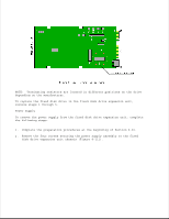
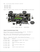
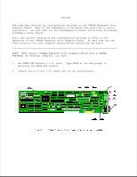
Chapter 9. Jumper and Switch Settings Chapter 9.1 Introduction This chapter provides jumper and switch settings for the COMPAQ PORTABLE 386 Personal Computer. When using the tables in this chapter, remember that the default settings shown are set for the system as configured by Compaq Computer Corporation. These settings need to be changed only when the system configuration is changed. If the jumpers are changed in a COMPAQ PORTABLE 386 Personal Computer, the SETUP program must be run to change the system configuration information stored in CMOS memory. Failure to run this procedure may result in Power On Self Test errors. The COMPAQ PORTABLE 386 Personal Computer has a configuration label, located on the inside of the rear panel, that shows the computers jumper settings. Chapter 9.2 System Board The COMPAQ PORTABLE 386 Personal Computer system board is a multifunctional board that provides configuration capability selections including: o Parallel Interface Options o Memory Size o System Operating Speed o Plasma Display Mode o Serial Interface Options The system board jumper settings are factory set for compatibility with most system applications. The functional capability of each jumper operates as follows: o E1, E2, and E7 set the parallel interface options. o E3, E4, E8, and E9 set asynchronous communications (serial) interface options. o E5 and E6 enable or disable the fixed disk drive and indicate whether the primary or secondary I/O address is used. o E13, E14, E15, E16, and E17 indicate the total amount of 32 bit RAM installed and determine how much RAM is to be used as base memory. o E19 enables or disables the fail safe timer. o E20 indicates whether or not an 80387 coprocessor is installed. o E21 selects either the AUTO or HIGH speed mode at power on. o E23 selects the plasma display mode at power on.
-
 1
1 -
2
-
3
-
4
-
5
-
6
-
7
-
8
-
9
-
10
-
11
-
12
-
13
-
14
-
15
-
16
-
17
-
18
-
19
-
20
-
21
-
22
-
23
-
24
-
25
-
26
-
27
-
28
-
29
-
30
-
31
-
32
-
33
-
34
-
35
-
36
-
37
-
38
-
39
-
40
-
41
-
42
-
43
-
44
-
45
-
46
-
47
-
48
-
49
-
50
-
51
-
52
-
53
-
54
-
55
-
56
-
57
-
58
-
59
-
60
-
61
-
62
-
63
-
64
-
65
-
66
-
67
-
68
-
69
-
70
-
71
-
72
-
73
-
74
-
75
-
76
-
77
-
78
-
79
-
80
-
81
-
82
-
83
-
84
-
85
-
86
-
87
-
88
-
89
-
90
-
91
-
92
-
93
-
94
-
95
-
96
-
97
-
98
-
99
-
100
-
101
-
102
-
103
-
104
-
105
-
106
-
107
-
108
-
109
-
110
-
111
-
112
-
113
-
114
-
115
-
116
-
117
-
118
-
119
-
120
-
121
-
122
-
123
-
124
-
125
-
126
-
127
-
128
-
129
-
130
-
131
-
132
-
133
-
134
-
135
-
136
-
137
-
138
-
139
-
140
-
141
-
 142
142 -
 143
143 -
 144
144 -
 145
145 -
 146
146 -
 147
147 -
 148
148 -
 149
149 -
 150
150 -
 151
151 -
 152
152 -
153
-
154
-
155
-
156
-
157
-
158
-
159
-
160
-
161
-
162
-
163
-
164
-
165
-
166
 |
 |