Compaq Presario 1800 Presario Select 1800 Series Maintenance and Service Guide - Page 84
Removing, the Battery, Charger, Board
 |
View all Compaq Presario 1800 manuals
Add to My Manuals
Save this manual to your list of manuals |
Page 84 highlights
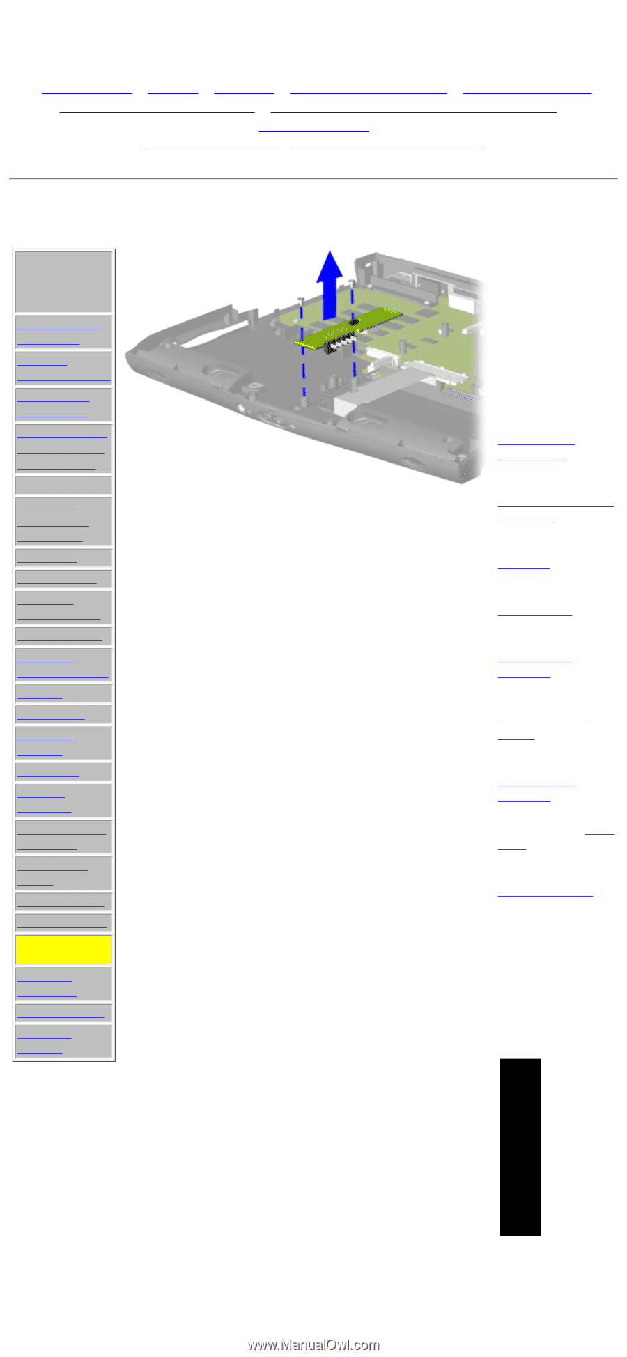
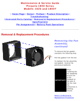
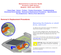
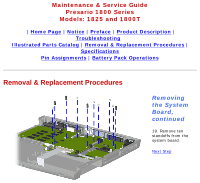
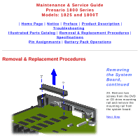
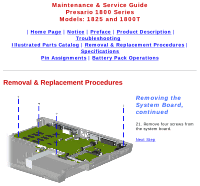
Maintenance & Service Guide Presario 1800 Series Models: 1825 and 1800T | Home Page | Notice | Preface | Product Description | Troubleshooting Illustrated Parts Catalog | Removal & Replacement Procedures | Specifications Pin Assignments | Battery Pack Operations Removal & Replacement Procedures Removal Sequence Electrostatic Discharge Service Considerations Cables and Connectors Preparing the Computer for Disassembly Battery Pack Palmrest Cover with Touch Pad Keyboard Status Panel Internet Button Board Heatspreader Network Interface Card Modem Hard Drive DisqPlay Module Processor DVD or CD Drive Display Panel Assembly Upper CPU Cover Fan Assembly Diskette Drive Battery Charger Board Speaker Assembly System Board Memory Module Removing the Battery Charger Board To remove the battery charger board, complete the following steps: 1. Prepare the computer for disassembly. 2. Remove the palmrest cover with touch pad. 3. Remove the keyboard. 4. Remove the heatspreader. 5. Remove the status panel assembly. 6. Remove the Internet Button board. 7. Remove the display panel assembly. 8. Remove the hard drive. 9. Remove the Upper CPU cover. 10. Remove two screws from the battery charger board, unplug the board from the connector on the system board, and lift out of the chassis. When replacing the battery charger board, ensure that NOTE: the pins are aligned with the connector on the system board. To replace the battery charger board, reverse the previous procedures.
-
 1
1 -
2
-
3
-
4
-
5
-
6
-
7
-
8
-
9
-
10
-
11
-
12
-
13
-
14
-
15
-
16
-
17
-
18
-
19
-
20
-
21
-
22
-
23
-
24
-
25
-
26
-
27
-
28
-
29
-
30
-
31
-
32
-
33
-
34
-
35
-
36
-
37
-
38
-
39
-
40
-
41
-
42
-
43
-
44
-
45
-
46
-
47
-
48
-
49
-
50
-
51
-
52
-
53
-
54
-
55
-
56
-
57
-
58
-
59
-
60
-
61
-
62
-
63
-
64
-
65
-
66
-
67
-
68
-
69
-
70
-
71
-
72
-
73
-
74
-
75
-
76
-
77
-
78
-
 79
79 -
 80
80 -
 81
81 -
 82
82 -
 83
83 -
 84
84 -
 85
85 -
 86
86 -
 87
87 -
 88
88 -
 89
89 -
90
-
91
-
92
 |
 |